
simple short circuit detection

This over-current protection circuit can be implemented using a combination of current sensing components, a comparator, and a relay or circuit breaker. The design typically includes a shunt resistor positioned in series with the load to measure the current flowing through the circuit. The voltage drop across this resistor is proportional to the current, allowing for real-time monitoring.
A comparator is employed to compare the voltage across the shunt resistor with a predefined threshold voltage, which corresponds to the maximum allowable current for the system. If the current exceeds this threshold, the comparator output changes state, triggering a relay or a circuit breaker to disconnect the load and prevent damage from over-current conditions.
In model train applications, the circuit can be finely tuned to accommodate the specific current ratings of various locomotives and accessories. This precision ensures that the protection mechanism activates only when necessary, allowing for optimal performance and minimizing unnecessary interruptions.
The circuit can be enhanced with features such as LED indicators to provide visual feedback regarding the operational status and fault conditions. Additionally, a reset mechanism can be integrated, allowing the user to easily restore functionality after resolving the short circuit issue.
Overall, this over-current protection circuit serves as a vital component in maintaining the reliability and safety of model train layouts, ensuring that enthusiasts can enjoy their hobby without the constant worry of damaging their equipment due to unforeseen electrical faults.This circuit is suitable in every situation where over-current protection is required. Here we give an example from the model train world. Every seasoned model train enthusiast knows that there is nothing worse than having to find the cause of a short-circuit. On a small model railway with one locomotive it is obviously fairly easy, but on large layouts all locomotives stand still when there is a short and then you have to check each one in turn to find the culprit..
🔗 External reference
Related Circuits
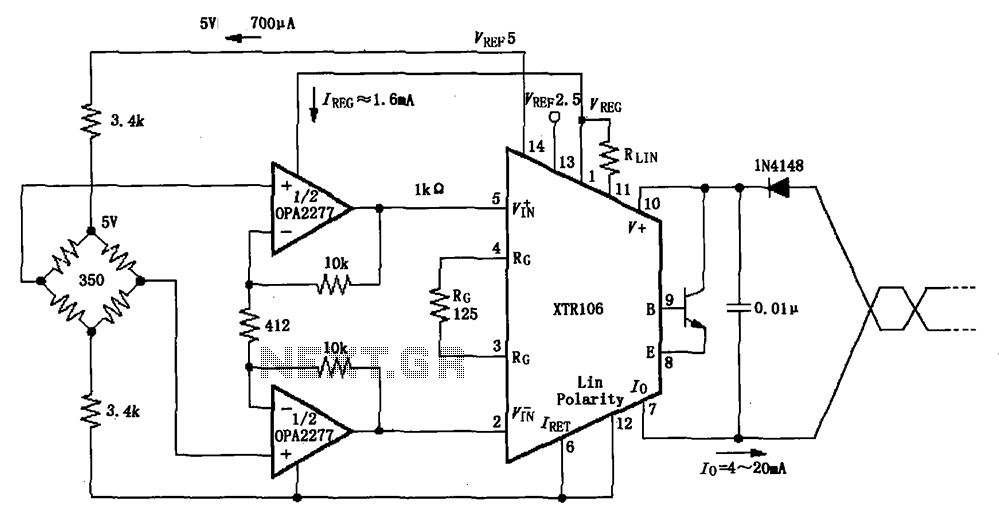
The XTR106, as illustrated in the figure, features two internal source voltages of 2.5V and 5V, enabling it to accommodate a wide range of bridge values without the need for additional circuitry. It can operate with bridge resistances lower...
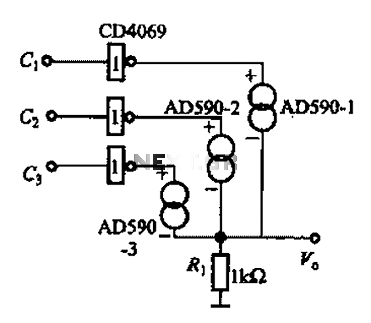
The AD590 is illustrated in a basic application circuit. As the AD590 provides a current output, a series resistance is used to convert this output current into a voltage. In the circuit, RP serves as the output voltage (vo)...
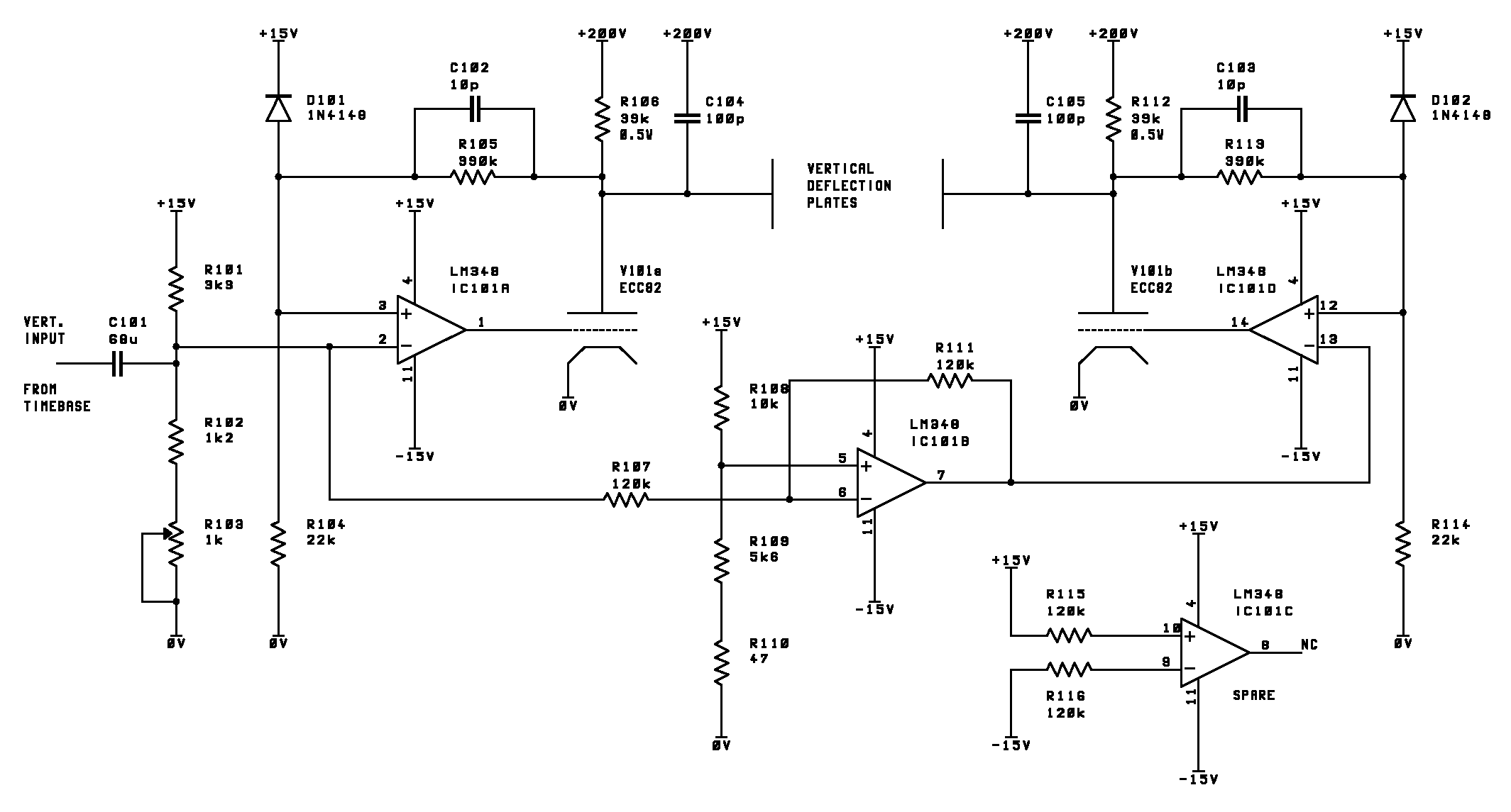
This page outlines the development of electronics for displaying a monochrome video image on an electrostatic oscilloscope tube. This work complements the Electron Optics section in the Experiments category. The primary objective is to showcase a moving video image...
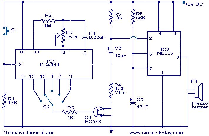
The following circuit illustrates a Selective Timer Alarm Circuit based on the 4060 Integrated Circuit (IC). Features include an automatic turn-off mechanism for the alarm after a specified duration. The Selective Timer Alarm Circuit utilizes the 4060 IC, which serves...
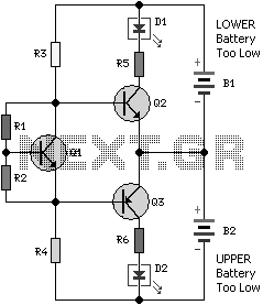
Most 24V power systems in trucks, 4WDs, RVs, boats, and similar applications utilize two series-connected 12V lead-acid batteries. The charging system is capable of maintaining the total voltage of the individual batteries. If one battery is experiencing failure, this...
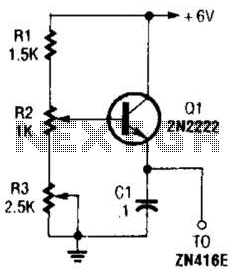
This regulator can be used with a +6-V source to supply the ZN416E low-voltage TRF radio receiver IC with the necessary +1.5 V. R3 sets the output voltage. The circuit utilizes a voltage regulator designed to convert a +6 V...