
Simple Light Sensor Alarm circuit with NE555

The circuit employs a 555 timer configured in an astable mode, which is ideal for generating a continuous square wave output. The LDR serves as a light-sensitive resistor whose resistance decreases significantly when exposed to light, thus allowing current to flow through the circuit. The output frequency of the 555 timer is determined by the resistor and capacitor values connected to it, with the frequency approximately set at 1 kHz in this application.
In this design, the LDR is connected in series with a resistor to form a voltage divider. When light falls on the LDR, its resistance drops, resulting in a higher voltage at the input of the 555 timer, triggering it to oscillate. The output from the 555 timer is fed into a transistor, which acts as a switch to control a larger load, such as a buzzer or alarm system.
The sensitivity adjustment feature, implemented through potentiometer P1, allows for fine-tuning of the light threshold at which the alarm activates. By varying the resistance, the circuit can be made more or less responsive to changes in light levels, providing flexibility in different lighting conditions.
Overall, this circuit is a practical solution for creating a light-activated alarm system, suitable for various applications such as security systems or alert mechanisms in environments where light levels need monitoring. The simplicity of the 555 timer circuit combined with the LDR sensor provides an effective and cost-efficient method for detecting light and activating an alarm.This circuit sent out an alarm when its LDR sensor is exposed to light by sun or lamp. A 555 astable multivibrator was used here which sent signal a tone of about 1kHz upon detecting light. The sensor when exposed by light completes the circuit and makes the 555 oscillate at about 1kHz with transistor to drive current.
Sensitivity can be adjust wit h P1. This makes the sun light to flow through it to the ground and prevents the alarm from going on due to the stored light on the sensor. 🔗 External reference
Related Circuits
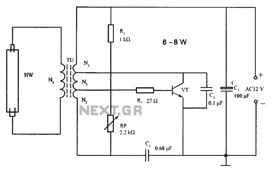
The lighting inverter circuit is designed for 6 to 8W fluorescent tubes. This circuit is appropriate for powering fluorescent tube circuits within the specified wattage. The parameters for the circuit are indicated in the accompanying figure. When utilizing a...

This project utilizes DTMF (dual-tone multi-frequency) signals, commonly used in telephones for dialing digits, as control codes. The DTMF tones are employed for frequency modulation of the carrier signal. At the receiver unit, these frequency-modulated signals are intercepted to...
The circuit was designed to create ten different frequency bands that can be processed by a single graphic equalizer to produce and maintain a predetermined frequency response. The described circuit is a graphic equalizer that utilizes a multi-band approach to...

This second issue of the Bikelab Notes, published during the development of BEHEMOTH at Sun Microsystems, focuses on high-brightness LED taillight assemblies that were not commercially available at the time, making this a unique project. The author also comments...
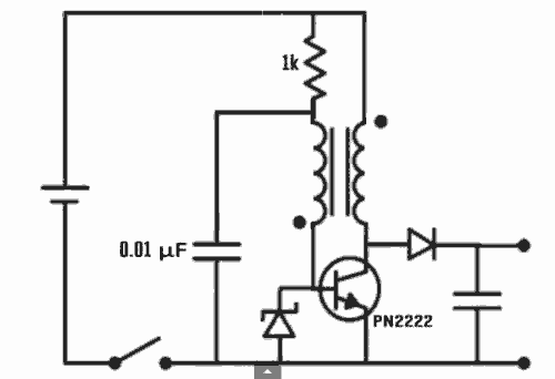
Excellent Joule thief circuit idea! The Joule Thief is a simple yet effective circuit designed to extract usable voltage from low-voltage power sources, such as depleted batteries. This circuit operates on the principle of boosting voltage through the use...
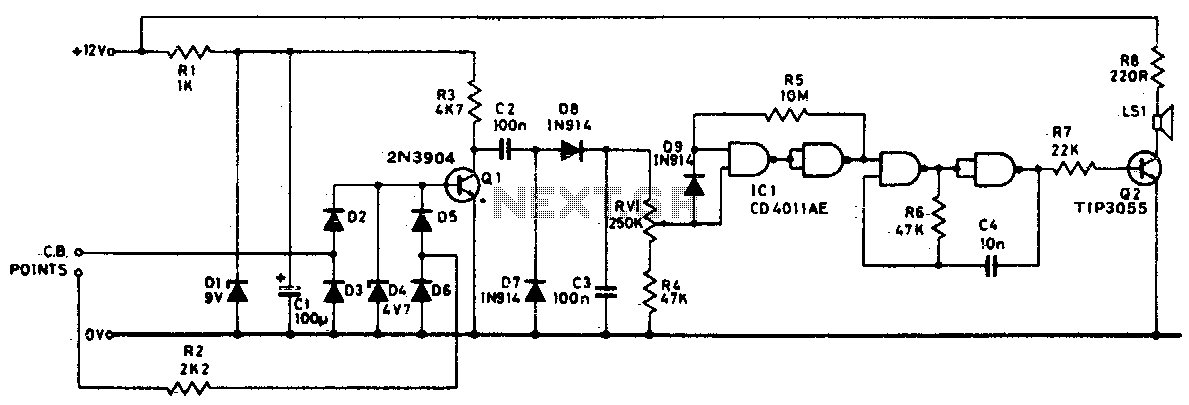
Pulses from the distributor points are passed through a current-limiting resistor, rectified, and clipped at 4 volts. Through Q1 and the diode pump, a DC voltage proportional to engine RPM is presented to RV1. The sharp transfer characteristic of...