
Speed alarm

The described circuit functions as a speed detection and alert system for vehicles, utilizing the pulses generated by the distributor points as a primary input signal. The initial stage involves a current-limiting resistor that ensures the pulse amplitude is suitable for subsequent processing, protecting the components from excessive current. The pulses are then rectified, converting the AC signal into a DC voltage, which is further clipped to a maximum of 4 volts to maintain a consistent voltage level for downstream components.
The transistor Q1 acts as a switch, allowing the rectified voltage to be fed into a diode pump. This arrangement boosts the voltage to a level that is proportional to the engine RPM, which is then directed to RV1, a variable resistor that may be used to calibrate the sensitivity of the circuit.
The CMOS gate, known for its sharp transfer characteristics, plays a pivotal role in determining the output signal. Feedback is utilized to stabilize the oscillation, which is generated by the unused half of the 4011 quad NAND gate. This oscillator produces a tone that can be heard through a connected speaker, serving as an alert system for the driver.
The design includes a specific threshold speed, at which the tone becomes audible. This threshold is critical as it provides a clear indication to the driver when the vehicle reaches a pre-defined speed. If the vehicle's speed decreases by three or four mph from this threshold, the tone ceases, thereby providing an effective and simple means of speed monitoring. The overall circuit is compact and efficient, making it suitable for integration into various vehicle systems.Pulses from the distributor points are passed through a current limiting resistor, rectified, and clipped at 4 volts. Via Q1 and the diode pump, a dc voltage proportional to engine rpm is presented to RV1; the sharp transfer characteristic of a CMOS gate, assisted by feedback, is used to enable the oscillator formed by the remaining half of the 4011
At the pre-set speed, a nonignorable tone emits from the speaker, and disappears as soon as the speed drops by three or four mph.
Related Circuits

The circuit diagram represents a brushless DC motor driving circuit designed for a 45V/8A application. It features an open voltage-controlled design that allows for speed adjustment through an external potentiometer connected to a PWM duty cycle. The diagram illustrates...

Greetings to all! A new user is exploring microcontrollers and is utilizing the AT89C55WD microcontroller to control an H-Bridge (L298), which subsequently drives a DC motor. The circuits for this setup are... The AT89C55WD microcontroller is an 8-bit microcontroller from...
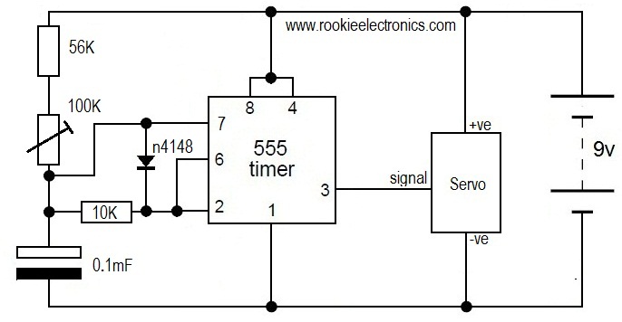
This is likely the simplest circuit to test a servo. It tests the speed of the servo using a potentiometer to control the speed. By applying a low voltage, such as 4.5V, and adjusting the potentiometer value, the position...
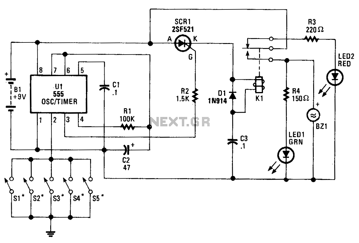
The core component of the circuit is a 555 timer/oscillator, designated as U1, which is configured for monostable operation. The output from U1 at pin 3 is connected to the gate of SCR1. As long as switches S1 to...

The change in ambient light triggers the alarm by changing the resistance of LDR1 and LDR2. The circuit utilizes two light-dependent resistors (LDR1 and LDR2) to detect variations in ambient light levels. LDRs are passive components that exhibit a change...
This circuit will allow you to control the speed of an AC motor, for example an electric drill. The way that this circuit works is as follows. The bridge rectifier produces dc voltage from the 120vac line. A portion...