
Simple LM317 variable voltage supply does it limit current too

In this circuit, a variable voltage supply is designed to provide a controlled output of 5V, adjustable via a potentiometer. The 240-ohm resistor serves as a current-limiting component, ensuring that the current flowing through the load does not exceed a predetermined value, thereby protecting sensitive devices such as LEDs or solenoids from damage due to excessive current.
To determine the appropriate power rating for the resistor, the maximum current limit must be calculated based on the desired output voltage and the resistance value. The power rating can be calculated using the formula P = I²R, where P is the power in watts, I is the current in amperes, and R is the resistance in ohms. If the expected maximum current is 500mA, the power dissipated by the resistor would be P = (0.5)² * 240 = 60 watts. Therefore, a resistor with a power rating significantly higher than this value should be selected to ensure reliability and prevent overheating.
In addition to the resistor, a current-limiting circuit may be implemented after the voltage regulator to provide further protection. This could involve the use of a transistor or an integrated circuit designed for current regulation, allowing for precise control over the maximum current supplied to the load.
The circuit should also incorporate safety features such as fuses or thermal protection to prevent damage in case of component failure or short circuits. By ensuring that the circuit design includes these considerations, the risk of damaging sensitive components while testing various loads can be minimized, allowing for a safe and effective testing environment.Assuming I can get 5V in example after adjusting the pot in real use, will the 240 ohm resistor limit the current, or do I have to add something else on top of that afterwards If it does (I can have var. voltage + current limit) I assume I will need to up the resistor power specifications as the current will flow through them (or my after-regulator limiter) Specifically, I do not want a constant current source, because testing
a home-made solenoid or a random LED I assume the upper current limit I set will let them work and not be destroyed. I want this because I wish to set a limit rather than force 500mA to go through something it does not want to by raising the voltage well above 5V for example.
🔗 External reference
Related Circuits
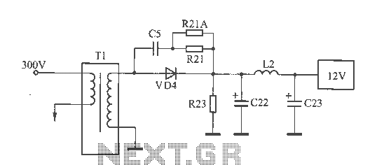
The 12V voltage instability should first be investigated by checking the output section of the switching power supply, as illustrated in the accompanying figure. The secondary winding of the transformer and the switch VD4 have been examined and found...
Similar to the CMOS-based touch switch available on this site, this transistor-based touch switch can activate a load simply by the user touching a metal plate. It is designed to directly switch a relay, allowing it to be used...
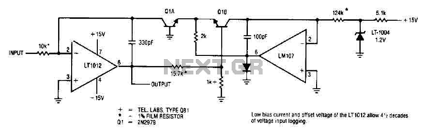
This simple logarithmic amplifier circuit uses the LT1012, which has a low bias current that allows for 4.5 decades of voltage input logging. Additionally, transistors that can be used in this circuit include the 2N2979. The logarithmic amplifier circuit designed...

This is a design for a sawtooth generator circuit. The advantage of this circuit is its low cost and the capability to produce an auxiliary square wave at the same frequency. This circuit can be utilized to sweep the...

This is an adjustable and regulated power supply with an output voltage range of 3V to 30V and a current supply capability of up to 3A. This circuit is equipped with short circuit protection and overload protection. The adjustable power...
The following circuit illustrates a simple light sensor circuit diagram. Features include crocodile technology for simulating circuit operation, and an LDR (Light Dependent Resistor) is utilized. The simple light sensor circuit operates on the principle of light intensity detection using...