
Simple Noise Limiter For Receivers Circuit

The diode series clipper circuit is designed to protect subsequent stages of a signal processing system from excessive voltage spikes that can occur due to noise or other interference. The circuit typically consists of a pair of diodes arranged in series with the input signal, which allows the circuit to "clip" or limit the amplitude of the incoming signal to a predefined level.
In operation, when the input voltage exceeds the forward voltage drop of the diodes, the diodes conduct and shunt the excess voltage to ground, effectively preventing the output voltage from rising above a certain threshold. This action helps to maintain signal integrity by reducing distortion caused by noise peaks.
The circuit is particularly beneficial in audio applications, where unwanted transients can lead to audible artifacts or damage to sensitive components. The effectiveness of the diode series clipper increases with the amplitude of the input signal; thus, it is best utilized in environments where the audio signal is several volts peak-to-peak.
In practical implementations, it is important to choose diodes with appropriate voltage and current ratings to ensure reliable operation. Additionally, the clipping level can be adjusted by selecting diodes with different forward voltage drops or by configuring the circuit with additional components, such as resistors or capacitors, to tailor the response to specific requirements. This circuit uses a diode series clipper to limit noise peaks on a received signal. It is best used where several volts p-p of audio signal are available.
Related Circuits
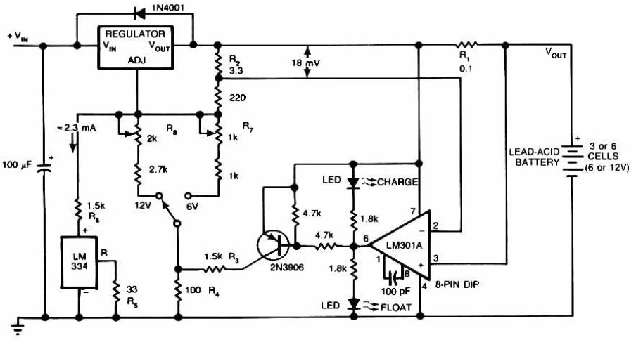
Lead-Acid Battery Charger circuit diagram. The LM301A compares the voltage drop across R1 with an 18 mV reference set by R2. The comparator's output controls the voltage regulator, forcing it to produce the lower float voltage when the battery-charging...
Can someone please help explain how this circuit works? I am confident that I understand how the voltage divider network operates. The circuit in question likely includes a voltage divider configuration, which is a fundamental concept in electronics used to...

When the system is placed in a shop or mall, logos and product advertisements serve as an ideal complement to temperature information. For home use, photographs of children at the beach or, should the temperature drop, images of making...
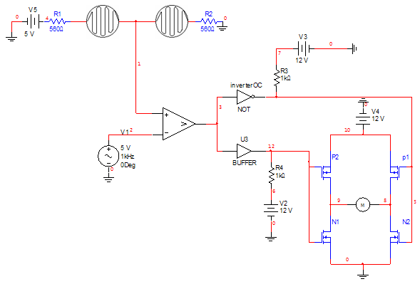
The circuit consists of inverter and charger sections. The inverter section utilizes the NE555 timer, while the charger section is based on the LM317 adjustable regulator. In the inverter section, the NE555 is configured as an astable multivibrator, generating...
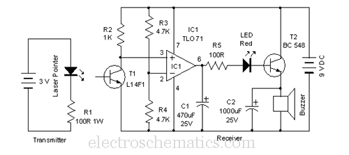
This laser door alarm operates by detecting the interruption of a laser beam. A low-cost laser pointer serves as the light source. When an individual crosses the path of the laser beam, it triggers the alarm. The laser door alarm...
Physical motion of some form helps differentiate a robot from a computer. It would be nice if a motor could be attached directly to a chip that controlled the movement. But, most chips can't pass enough current or voltage...