
Simple optical switchs

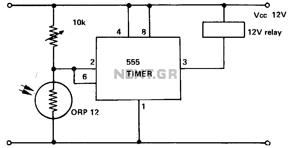
The circuit described utilizes a phototransistor in conjunction with a 555 timer integrated circuit (IC) to create a light-sensitive triggering mechanism. The phototransistor serves as a light sensor, responding to IR light. Upon detecting sufficient IR light, the phototransistor conducts, resulting in a voltage drop across the connected resistor. The 555 timer monitors this voltage, and when it falls below the specified threshold (VCC/3), it activates its output.
The choice of the resistor value is critical in setting the sensitivity of the phototransistor. A lower resistance value is suitable for high-sensitivity phototransistors, allowing them to trigger the 555 timer with minimal light input. Conversely, a higher resistance is appropriate for less sensitive phototransistors, requiring more light to reach the threshold. The use of a trimmer potentiometer enables fine-tuning of this threshold, allowing for greater flexibility in various applications.
The 555 timer's output capabilities make it suitable for driving a wide range of devices. Its high current output can control relays or transistors, enabling the circuit to switch larger loads or provide logic signals based on the detected light levels.
For applications where the output needs to be inverted (e.g., triggering an alarm when light is blocked), the circuit can be modified using a bipolar transistor configured as an inverter. This allows the system to respond appropriately to changes in light conditions, enhancing its functionality in security or control systems.
Overall, this circuit design is versatile and can be adapted for various applications requiring light detection and response, emphasizing the importance of component selection and configuration in achieving the desired performance.When the phototransistor is stroken by IR light it conducts and the voltage between the 1Mohm resistor(arbitrary) and the phototrans drops from VCC to lower values. When the voltage drops lower than VCC/3 the 555 is triggered and goes high (from 0 TO VCC). The amount of light that strike the phototrans necessary to bring his collector to VCC/3 is determined by the resistor (Vdrop = Icollector * R, so, if Vdrop= 2*VCC/3, the resistance needed to set the threshold on current is R=2*VCC/(Icollector*3). High sensibility phototrans would need a smaller resistor, and weaker phototransistors higher value resistor, you can also use a trimmer to set the on threshold level with precision.
The time of phototransistor isn`t critical. The 555 has high current capability and can drive various devices, such as Bipolars, relays, bipolars+relays, mosfets, mosfets + totem pole, or give a logic output (see pic). In case you need to trigger something when the gate is blocked (for example a burglar alarm, or a multistage coilgun) you need to invert the output, which is accomplished using a small bipolar transistor wired in an inverting setup (see pic) or swapping the positions of phototransistor with the resistor, so the voltage will drop under VCC/3 when blocked: The formula to determine the resistance to turn off at Icollector is R=VCC/(Icollector*3).
🔗 External reference
Related Circuits
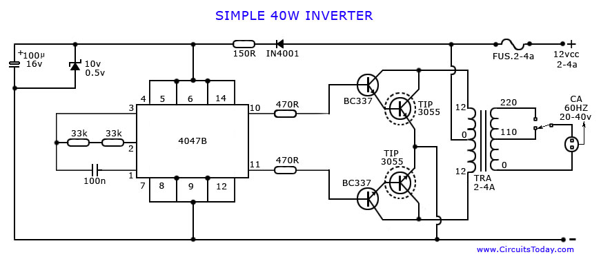
An article on how to create an inverter using a simple 40-watt inverter circuit diagram and schematics. This inverter converts 12 volts to 220 volts using the CD4047 integrated circuit. The described inverter circuit utilizes the CD4047 IC, which is...
A voltage-to-frequency converter can be constructed using the LM231/331 chip, making it a cost-effective solution for applications such as analog-to-digital conversion and frequency-to-voltage conversion over extended periods. The LM231/331 series of voltage comparators can be effectively utilized to design a...
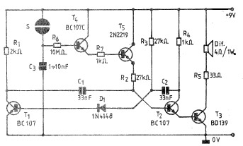
A simple and practical electronic bell circuit can be constructed using the provided schematic diagram. This circuit can function as a doorbell or an alarm system. It utilizes only a few transistors along with several common components. The circuit...
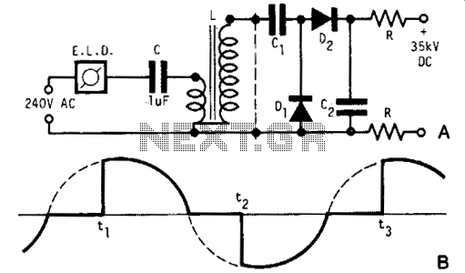
A light dimmer, a 1 µF capacitor, and a 12 V car ignition coil form a simple line-powered high-voltage generator. The current in the dimmer is illustrated in Fig. B. During the time intervals tp to t2, determined by...
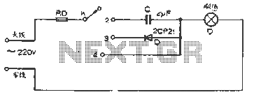
The figure illustrates a basic dimming lights circuit. The light intensity is controlled by a multi-speed control switch, designated as K. When switch K is set to position "1," the lights are turned off. In position "2," the light...
This circuit illustrates a 555 timer with its trigger and threshold inputs connected together, which is utilized to activate a relay when the light level detected by a photoconductive cell drops below a predetermined threshold. Additionally, this circuit can...