
Simple receiver with microvolt sensitivity

This three-transistor circuit is designed for efficient short-wave radio signal reception, leveraging a cost-effective and compact approach. The circuit's architecture includes a regenerative amplifier stage with Q1, which is pivotal for boosting weak signals captured by the antenna. The choice of a bipolar transistor for Q1 is significant, as it provides a high transconductance, enabling substantial amplification from minimal current input. The regenerative feedback mechanism enhances the selectivity of the circuit, allowing it to distinguish between closely spaced frequencies, which is essential in crowded radio bands.
Components R1 and R2 are critical for establishing the operating point of Q1, ensuring that the transistor remains in its active region while providing the necessary negative feedback to control the regeneration. The adjustable resistor R3 permits fine-tuning of the regeneration level, allowing users to optimize performance based on specific reception conditions. The subsequent amplification stages, Q2 and Q3, are designed to deliver sufficient output power to drive audio output devices, ensuring that the audio signal is clear and audible.
The inclusion of a low-pass filter formed by R4 and C4 is essential for reducing high-frequency noise that could degrade audio quality. This filter works by allowing only the desired audio frequencies to pass while attenuating unwanted signals. The voltage regulation provided by D2, D3, and D4 is a noteworthy feature, as it stabilizes the power supply to Q1, which is crucial for maintaining consistent performance and minimizing drift in signal reception.
The circuit's low power consumption, particularly in the regenerative stage, is a significant advantage, as it reduces the risk of interference with other receivers. This characteristic is particularly beneficial in environments where multiple receivers may be operating simultaneously. Overall, this three-transistor circuit exemplifies an effective solution for short-wave radio reception, balancing performance, cost, and component availability.The three-transistor circuit in Fig 1 costs less than $10 to build, uses commonly available components, and consumes less than 10 mA from a single 9V battery. If you wind coil L1, as the figure shows, the circuit receives signals in the 5- to 15-MHz short-wave band.
You can add turns to or subtract turns from L(or change C2) to receive other frequ encies. Q1, a 10 bipolar transistor, acts as a high-gain regenerative stage and amplifies microvolt-level signals at the antenna up to hundreds of millivolts to drive diode-detector D1. In addition to providing high gain, regeneration also greatly increases the Q (selectivity) of the circuit, producing a high-Q circuit, which can use low-cost coils (or free hand-wound coils).
Using a high-transconductance bipolar transistor for Q1 rather than a vacuum tube or JFET provides much more gain per microamp of current. However, in previous bipolar circuits of this type, the regeneration level has been difficult to control.
In this circuit, R1 and R2 provide a large amount of negative bias at the emitter of Q1 to achieve smooth control. Rallows for user control of the regeneration. You should adjust the pot so that Q1 is just at the threshold of oscillation where both gain and selectivity are maximum.
Q2and Q3, a two-transistor amplifier, which has sufficient output level to directly drive headphones or a small speaker, amplify the detected audio signal output from D1. R3can become a volume control if you replace it with a 2-kOhms potentiometer and connect C3to its wiper.
R4 and C4 form a lowpass filter that maintains circuit stability and improves the receiver`s sound quality. D2, D3, and D4 implement a low-cost voltage regulator to keep the voltage supplying Q1fairly constant, which minimizes drift.
This receiver works with a short whip antenna, which you can connect directly to the top of tuning-capacitor C2, or you can use an outside antenna for better reception. When you use an external antenna, Cmust decouple the antenna`s capacitance from L1. The regenerative stage of Q1operates at less than 30 µW (50 µA at 0. 6V). This low power, combined with the use of a small capacitor for C1, prevents the detector (if it oscillates) from interfering with other receivers in the area.
This problem was common in the 1920s and 1930s when tube-type regenerative receivers of this type, dissipating several watts of power, caused interference. 🔗 External reference
Related Circuits
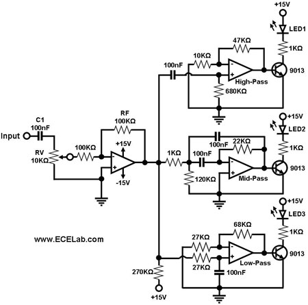
Figure 1 illustrates a simple circuit designed for converting an audio signal (such as one from the output terminals of a CD player). The circuit primarily consists of a buffer/amplifier stage and three filtering circuits: a high-pass filter, a...
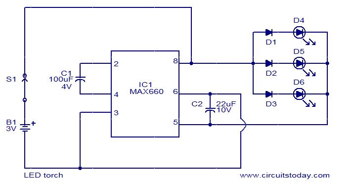
This circuit is a simple LED torch utilizing the MAX660 integrated circuit from MAXIM semiconductors. The MAX660 is a CMOS monolithic voltage converter IC capable of driving three bright white LEDs connected in parallel to output pin 8 of...
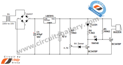
This is a straightforward 12V rechargeable smart battery charger circuit. It can be utilized as a charger for car batteries, inverter batteries, emergency light batteries, and more. An automatic indicator alarm circuit accompanies this battery charger schematic. The primary...

The utility vehicle anti-theft alarm circuit consists primarily of two main components essential for its operation. The security circuit is activated when the vehicle owner departs from the vehicle, utilizing an anti-theft switch (S B) to engage the alarm...
The schematic for the crystal bandpass filter/amplifier board is illustrated, along with images of the assembled and boxed unit. The signal frequency bandpass filter is constructed over a ground plane and enclosed in a separate housing measuring 75 x...
This simple door chime protects the door and emits a loud alarm tone in the event of a theft attempt. The circuit is straightforward and battery-operated. A Normally Closed (NC) reed switch and magnet are utilized to trigger the...