
Simple RF field meter with LM358

The RF field meter circuit operates by utilizing a dipole antenna, which is specifically designed to resonate at a particular frequency. The antenna dimensions can be calculated using the formula provided, ensuring optimal performance in receiving RF signals. The received RF energy is captured by the dipole antenna and subsequently fed into a rectifying diode. The diode converts the alternating current (AC) RF signal into a direct current (DC) voltage, which is initially at a low level and requires amplification for effective measurement.
The operational amplifier (OP) is configured to amplify the rectified DC voltage. The gain of this amplifier can be adjusted using a potentiometer, allowing for fine-tuning based on the expected signal strength. Following this, a second operational amplifier is employed as a voltage follower, ensuring that the output voltage is stable and can be used to set the zero offset for the panel meter. This configuration is crucial for accurate readings, as it allows the operator to calibrate the meter to zero when no RF signal is present.
To mitigate the effects of RF interference on the panel meter readings, the circuit incorporates ferrite blocks along the 5-meter wire connection to the panel meter. These ferrite blocks act as high-impedance elements, effectively filtering out unwanted RF signals that could distort the readings. The choice of ferrite or a large inductor (10uH) can provide flexibility in component selection while maintaining performance.
The panel meter serves as the primary output display for the RF field meter, providing a visual representation of the RF field strength. Although the device does not measure power in absolute terms, it offers relative readings that are sufficient for tuning purposes. The operational procedure involves placing the RF field meter at a distance from the transmitter, adjusting the gain for optimal readings, and calibrating the offset to ensure accurate zeroing of the meter.
In summary, this RF field meter circuit provides a practical solution for tuning RF transmitters by measuring the strength of the RF field in real-time. Its design emphasizes ease of use, accurate measurement, and flexibility in component selection, making it a valuable tool for RF enthusiasts and professionals alike.This project will explain the function of a simple RF field meter. The unit will be in great help to tune transmitters for best performances. At the bottom left corner you will see a voltage divider. This divider is to produce a virtual ground of 4.5VDC. Above you will find the dipole antenna. The dipole antenna will pick up some radiated energy and the diode will rectify the RF signal to a DC voltage at VRF. This voltage is still quit low and needs to be amplified before it can control the panel meter. The signal then enter the OP which amplifies the voltage to suitable level set by the "Gain" potentiometers".
The second OP acts as a voltage follower and set the offset (zero) for the panel meter. The panel meter is connected to the board via two wires (5meter long). To prevent any RF signal to be induced in this long wire I have added 2 ferrite block which will act as high impedance units. You can use any ferrite block or large inductor (10uH). The block diagram at right show you one easy way to measure the RF filed strength. To the left you find a dipole antenna. The antenna should be cut to match the receiving frequency. The length of antenna is not a critical at all. Length = 0.95*300/(4*freq) <= (freq = Mhz) The RF signal is then rectified in a diode and the DC voltage is then amplified in an OP-amplifier. To display the voltage I use a panel meter. The amplifier gain can be set with a potentiometer and I have also added a bias voltage to set the zero level of panel meter. This unit will not show you the exact power like a power meter, but it will show you the relative power transmitted out from your transmitter and antenna.
The panel meter is connected to the PCB with 5 meter long wire. In this way I can put the field-meter 5m away from where I am and still be able to watch the panel meter. I will tell you how I use my filed meter. I place the RF field meter 5 meter away from my transmitter. I then put all variable capacitor to middle. I switch on the transmitter and go to my RF filed meter. I then set the gain (with potentiometer) so I get half of max reading on the panel meter. I then switch off the transmitter and set the offset (with other potentiometer) so I get zero reading on the panel meter.
I repeat this tuning process unit it looks good. Now I can start tuning the transmitter and watch the panel meter. All I need to do is to tune for max reading on the panel meter. Then I know the RF field is at max strength. I also advice you too receive the signal you are transmitting to check that it sound good. I also check the current to the transmitter so it don't get to high. Usually the current go down when good tuning has been done and you got max power. Another good thing to monitor is the temperature of the transistors. Don't let them go to hot. 🔗 External reference
Related Circuits
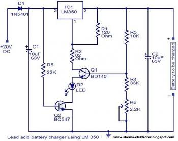
The circuit is designed as a constant voltage source with a negative temperature coefficient. The transistor Q1 (BD 140) serves as the temperature sensor, while transistor Q2 prevents battery discharge through resistor R1 when mains power is unavailable. The...
Here is a simple schematic of one of the components. The concept is that if the probed voltage is below half of the reference voltage, one LED will illuminate; otherwise, the second LED will turn on. Additionally, there is...
There will be many times where it is desirable to use the P05 supply module from a higher voltage source. For example, if you want to add balanced inputs to a power amplifier, then you need a +/-15V supply,...

This circuit is used for a Digital Radar Speedometer. It allows for the measurement of the speed of any moving object, particularly vehicles such as cars. The speed is displayed in kilometers per hour (KPH) with a three-digit display....
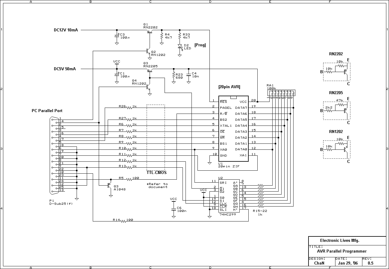
These are simple AVR programmers. I designed and built four different programmers for various environments: LPT controlled parallel programmer, LPT controlled ISP adapter, COM controlled ISP adapter, and COM controlled generic SPI bridge. Additionally, COM controlled adapters can be...
This ultra-simple remote control extender is ideal for use with a hidden video recorder. The recorder is a Panasonic NV-SD200 and is employed as part of a camera surveillance system. A PICAXE-08-based circuit detects events and controls the recorder....