
Simple RF Transmitter

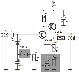
The tone transmitter schematic operates primarily on the principle of frequency modulation (FM). The circuit typically includes an oscillator, which generates a carrier wave at a specific frequency. The oscillator's frequency can be influenced by the resistance of the carbon microphone, which acts as a variable resistor. When voice signals are applied to the microphone, it changes the resistance, thereby modulating the frequency of the oscillating signal.
The circuit design may incorporate a coil, which serves as an inductor, and a capacitor, forming an LC circuit that determines the oscillation frequency. Proper selection of the inductor and capacitor values is crucial, as they dictate the frequency range of the transmission. The use of a carbon microphone allows for the conversion of sound waves into electrical signals, which can then be transmitted as frequency-modulated waves.
For practical implementation, ensuring a stable power supply is essential, as fluctuations can affect the signal quality. Additionally, the physical arrangement of components can influence performance. For instance, mounting the coil to a window can enhance sound capture by utilizing the window's surface to pick up vibrations from surrounding audio sources.
When considering demodulation, it is important to implement a suitable demodulator circuit to recover the original audio signal from the modulated carrier wave. Common demodulation techniques include envelope detection and phase-locked loops (PLLs), which can effectively extract the audio signal for playback or further processing.
Overall, the tone transmitter circuit offers a unique approach to audio transmission, leveraging simple components to achieve frequency modulation. Further experimentation and refinement may yield improved performance and practicality for voice transmission applications.This schematic is a tone transmitter. For sufficiently small values of the resistor, it outputs a tone, so having a resistive mic (carbon mic) in parallel with or in place of the resistor. would modulate the tone frequency with the voice. I`m not sure how you`d be able to demodulate it though, so this may not be the best circuit to use as a voice transmitter.
Sorry about my last post (and for bumping), it would NOT go in place of the capacator but as said before, it would be used like a resistor to control the capacitor. Hi All that is a very interesting cct. I built one almost exactly the same and it was shown as an FM transmitter. I. e. frequency modulated. Sure enough I could pick the carrier up on my FM radio about mid way on the scale. I was wondering how to put the audio/voice signal in when I noticed tapping and knocking noises coming up on the radio and a moved my physical circuit around !. The wound coil was vibrating and altering the frequency which was of cource then being picked up on the FM receiver as frequency modulated signal !
So for a microphone you could try glueing the circuit to a bit of brick and attaching the coil to a window. That way the window would pick up voice signals and mechanically feed them like a big microphone through the circuit into the FM radio receiver.
I havent tried this yet but if I see any replies to this post I will get my circuit out again as I still have it and a few other similar ones I was playing with for my data transmission project. 🔗 External reference
Related Circuits
Here is a very simple, inexpensive and interesting project which provides lot of fun to a home experimenter or hobbyist. This simple transmitter can transmit speeches or songs within a short range. The circuit uses only one transistor. The...
The transmitter circuit described here includes an additional RF power amplifier stage following the oscillator stage, which increases the power output to 200-250 milliwatts. When used with a properly matched 50-ohm ground plane antenna or a multi-element Yagi antenna,...
Square wave generators are typically based on symmetrical multivibrators using bipolar transistors of the same structure, along with two frequency-determining networks. However, a simpler oscillator can be constructed with two transistors of different structures (refer to figure 1) utilizing...
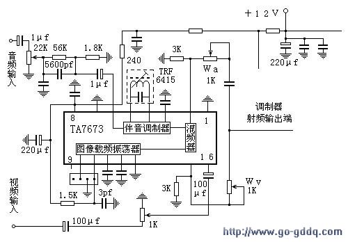
The circuit design philosophy allows for debugging without any RF instruments. Although its performance may not match that of professional equipment, it should be adequate for hobbyists, with audio-visual transmission effects comparable to general-purpose machines. The transmitter consists of...
The video amplifier in the diagram represents a well-established design that is both simple and highly functional. However, it is important to note that the transistors can be easily damaged if the potentiometers (black level and signal amplitude) are...
L2 RFC (resistance 1MOhm with an inductor wrapped around it made from fine isolated wire. Scratch the inductor and connect it to the resistance, creating a parallel L-R circuit.) With C7 and C8, we adjust the resistance of the...