
Simple Short-Wave Transmitter
The short-wave transmitter operates within a frequency range of 10 to 15 MHz, making it suitable for various communication applications. The primary frequency-determining component is the ½J gang condenser VC1, which, in combination with inductor L1, allows for precise tuning of the carrier frequency. The inclusion of VC2 for frequency trimming ensures that the transmitter can be finely adjusted for optimal performance.
Transistor T4 plays a crucial role in amplifying the carrier signal, which is then passed to the RF amplifier transistor T1 (BD677) through transformer X1. The absence of a modulator transformer simplifies the design and reduces costs, making this transmitter an economical choice for hobbyists and educational purposes.
The audio input from the condenser microphone is first preamplified by transistor T3 (BC548), providing a stronger signal for further amplification. The amplified audio signal is then fed into transistor T2 (BD139), which modulates the RF signal. This modulation is achieved by varying the current through the RF amplifier based on the audio signal's amplitude, allowing for effective transmission of audio signals over the RF carrier.
RFC1 is an RF choke that serves to isolate the modulated RF signal from the power supply, ensuring that the audio modulation does not interfere with the power circuitry. The modulated RF signal is then coupled to the antenna through capacitor C9, which blocks any DC components while allowing the RF signal to pass.
The design incorporates a 0.5m long telescopic aerial as the antenna, which is sufficient for short-wave transmission and reception. The use of a ready-made short-wave antenna coil with a tuning slug (Jawahar make) for the RF choke, inductor L1, and coupling transformer X1 enhances the reliability and performance of the transmitter. Testing has shown that the transmitter can achieve good signal strength with reception distances up to 75 meters, making it suitable for various practical applications in short-wave communications.This low-cost short-wave transmitter is tunable from 10 to 15 MHz with the help of ½J gang condenser VC1, which determines the carrier frequency of the transmitter in conjunction with inductor L1. The frequency trimming can be done with VC2. The carrier is amplified by transistor T4 and coupled to RF amplifier transistor T1 (BD677) through transf
ormer X1*. The transmitter does not use any modulator transformer. The audio output from condenser MIC is preamplified by transistor T3 (BC548). The audio output from T3 is further amplified by transistor T2 (BD139), which modulates the RF amplifier built around transistor T1 by varying the current through it in accordance with the audio signal`s amplitude. RFC1 is used to block the carrier RF signal from transistor T2 and the power supply. The modulated RF is coupled to the antenna via capacitor C9. For antenna, one can use a 0. 5m long telescopic aerial. Details of RF choke, inductor L1 and coupling RFC1 is used to block the carrier RF signal from transistor T2 and the power supply.
The modulated RF is coupled to the antenna via capacitor C9. For antenna, one can use a 0. 5m long telescopic aerial. Details of RF choke, inductor L1 and coupling transformer X1, we used a ready made short-wave antenna coil with tuning slug (Jawahar make), which worked satisfactorily. We tested the transmitter reception up to 75 metres and found good signal strength. 🔗 External reference
Related Circuits
This circuit addresses the challenge of transmitting data over a cable that lacks available conductors. The data is modulated using On-Off Keying (OOK) and superimposed on a high-frequency carrier, allowing it to be transmitted over a low-voltage power supply...
This circuit explains alternate wireless switching using an ultrasonic sensor. The distance of the switching range should be more than 10 meters. The described circuit employs an ultrasonic sensor to facilitate wireless switching, allowing for the activation or deactivation of...
An increasing number of appliances draw a very small current from the power supply. When designing a mains-powered device, one can typically choose between a linear power supply and a switch-mode power supply. However, if the total power consumption...
Output-clamp diodes are mandatory because loudspeakers are inductive loads. Output LR isolation is also used because audio amplifiers are usually expected to handle up to 2 mF load capacitance. Large, supply-bypass capacitors located close to the IC are used...
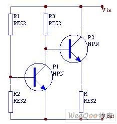
When the current is below the specified threshold, the bias current supplied by resistor R1 causes transistor P3 to saturate and conduct. In this state, it is unable to regulate the current effectively. Conversely, when the current reaches or...

This is a simple 1-watt FM transmitter circuit that is easy to construct. It consists of four transistors, one of which serves as a stable oscillator. This is followed by a buffer stage to minimize frequency variations when adjusting...