
Simple Stepper Motor Controller

A stepper motor controller is an essential component for the effective operation of stepper motors, which are widely used in various applications requiring precise control of position, speed, and torque. Unlike standard DC motors, stepper motors require specific control signals that dictate their movement in discrete steps. This characteristic enables them to achieve high precision in positioning without the need for feedback systems.
The controller typically interfaces with a microcontroller or a computer to receive commands regarding the desired movement. It converts these commands into a series of electrical pulses that are sent to the stepper motor. Each pulse corresponds to a specific step of the motor, allowing for controlled rotation in either direction. The controller can also manage the speed of the motor by adjusting the frequency of the pulses.
There are various types of stepper motor controllers, including unipolar and bipolar configurations, each designed to drive different types of stepper motors. Unipolar controllers often simplify the control mechanism by allowing current to flow in one direction through the motor coils, while bipolar controllers provide greater torque and efficiency by enabling current to flow in both directions.
In addition to basic functionality, advanced stepper motor controllers may include features such as microstepping, which allows for smoother motion and finer resolution by dividing each full step into smaller increments. This is particularly useful in applications requiring high precision, such as CNC machines or 3D printers.
Overall, a stepper motor controller is crucial for harnessing the full capabilities of stepper motors, enabling applications that demand accurate and reliable motion control.Stepper motor controller is needed to run a stepper motor, since a stepper motor cannot work by just connecting it to a power supply. ?To program a stepper. 🔗 External reference
Related Circuits
The water level controller circuit described here controls the water level inside a tank. There are two modes available with this water level controller circuit. The water level controller circuit is designed to maintain the water level within a specified...
The circuit involves powering an LED using a 3V CR2032 battery, with the intention of extending battery life by making the LED blink rather than remain continuously on. A 555 timer is considered, utilizing large value resistors in the...
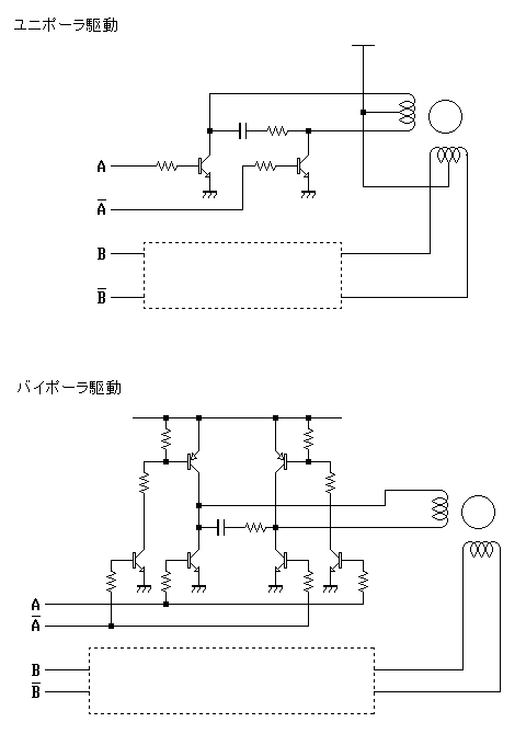
The first pulse motor that is used to position control. Features were incorporated for positioning control. This does not mean intelligent and autonomous driving the motor in response to movement commands from the host. The key to controlling the...
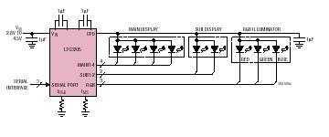
The LTC3205 is a highly integrated multidisplay LED controller. The part contains a high efficiency, low noise fractional step-up/step-down charge pump to provide power for both main and sub white LED displays plus an RGB color LED display. The...
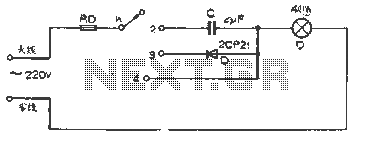
The figure illustrates a basic dimming lights circuit. The light intensity is controlled by a multi-speed control switch, designated as K. When switch K is set to position "1," the lights are turned off. In position "2," the light...
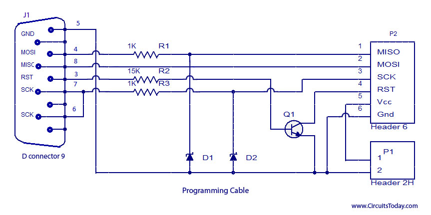
ISP programmer with circuit diagram for AVR Atmega32 microcontroller. This ISP burner circuit is an adaptation of the Pony programmer and uses PonyProg software. The ISP (In-System Programming) programmer designed for the AVR Atmega32 microcontroller allows for programming the microcontroller...