
Simple Touch Alarm circuit

This description outlines a basic touch-activated alarm system. The circuit typically consists of a touch-sensitive sensor, a microcontroller, a sound output device (such as a buzzer or speaker), and a power supply.
The touch-sensitive sensor can be implemented using capacitive or resistive technology, which detects the presence of a finger through changes in capacitance or resistance. Upon detection, the sensor sends a signal to the microcontroller, which processes the input.
The microcontroller is programmed to activate the sound output device for a predetermined duration once the sensor is triggered. This duration can be adjusted in the firmware to suit the application. After the set time elapses, the microcontroller deactivates the sound output, effectively silencing the alarm.
When the sensor is touched again, the process repeats, allowing for multiple activations. The circuit may also include additional features such as LED indicators to provide visual feedback during activation or a reset mechanism to stop the alarm after a certain number of activations.
Power management is crucial in such designs, especially if the device is battery-operated. The circuit can include a low-power mode to conserve energy when not in use. Overall, the schematic for this touch-activated alarm would include the sensor, microcontroller, sound output, power supply, and any additional components for functionality and user interface.Touch the sensor of the alarm with your finger and it starts beeping, goes on for some time and then stops. Touching it again, and it goes again! This litt. 🔗 External reference
Related Circuits
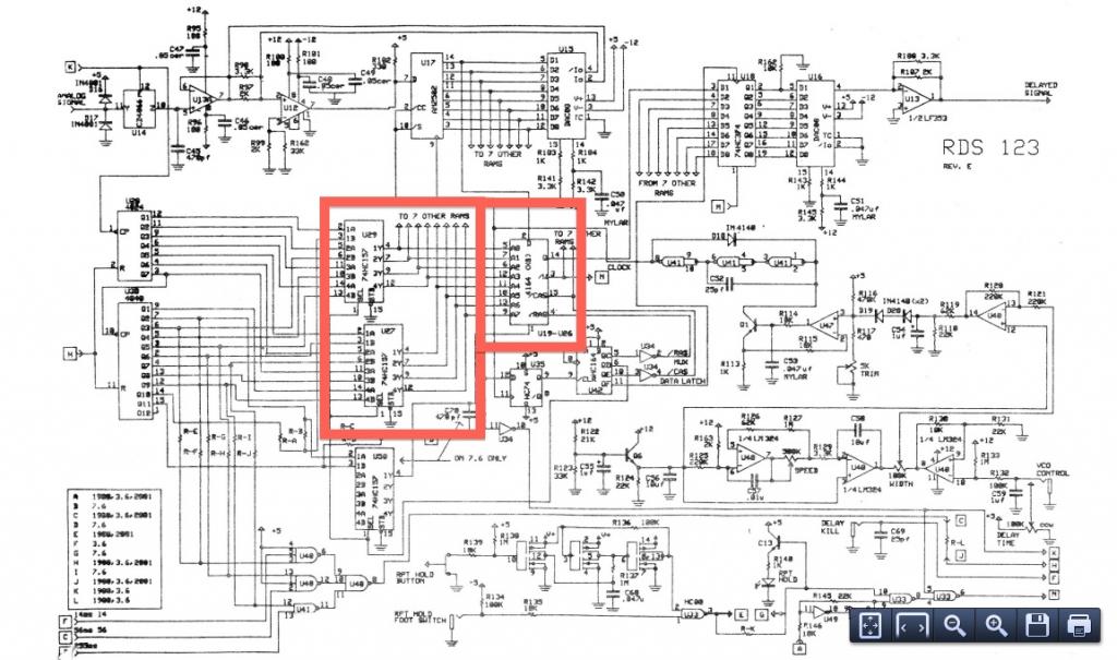
This project is suitable for individuals who enjoy experimenting with electronics. It presents a low risk of damaging the unit. This project involves creating a simple electronic circuit that allows users to engage in hands-on experimentation without significant risk. The...
Is the battery depleted, or is there an issue with the device? This question often arises when a battery-operated device, such as a Walkman, fails to power on. Before seeking professional repair services, it is advisable to first test...

An automatic Ni-Cd battery charger circuit is depicted in the provided image. The internal comparator of the NE555 timer is configured to a reference voltage of 4.7V using a Zener diode. When the voltage at pin 6 exceeds this...
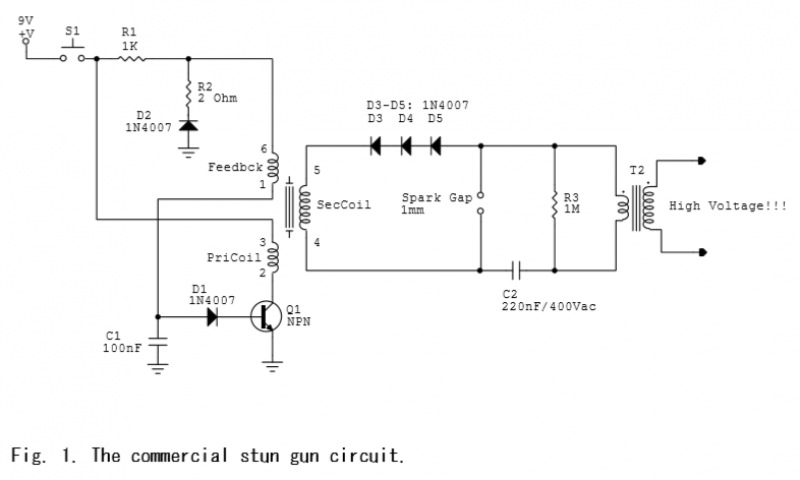
A commercial stun gun circuit that generates approximately 100 kV pulses from a 9V battery is illustrated in Figures 1-2. The core of the circuit is a power oscillator centered around transistor Q1. When switch S1 is activated, capacitor...
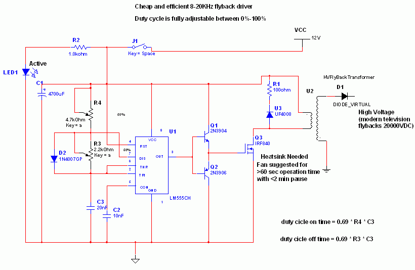
Many sites do not provide circuits for driving these transformers; they simply state that they are ineffective. However, this assertion is contested. A circuit has been developed that operates effectively, with significant effort invested in determining the resonant frequency...

Almost all DC amplifier circuits are utilized as the input stage of differential circuits. Many complementary symmetry circuits also employ a double differential complementary sub-circuit along with a constant current source for the input stage. The constant current source...