
Simple Under-Voltage Cut-Out

Sensitive low-current relay coils are designed to function effectively at specified voltage ratings; however, they may exhibit erratic behavior when operating at lower-than-expected supply voltages. This issue can lead to unreliable performance in various applications, particularly in systems where precise operation is critical. To mitigate this problem, the incorporation of a zener diode in series with the relay coil is a recommended approach.
The zener diode serves as a voltage clamping device, effectively limiting the voltage applied to the relay coil. When the supply voltage exceeds the zener breakdown voltage, the diode conducts, thereby reducing the voltage across the relay coil. This results in the relay dropping out at a lower voltage threshold, which can enhance the stability of the system under low-voltage conditions.
Furthermore, integrating a light-emitting diode (LED) into the circuit can provide a visual indication of the relay's status. If spare "normally closed" contacts are available on the relay, the LED can be wired in such a way that it illuminates when the relay is in the dropout state. This visual feedback can be invaluable for troubleshooting and monitoring system performance, ensuring that operators are aware of the relay's operational status at all times.
The design considerations for this circuit must include the selection of an appropriate zener diode that matches the specific voltage requirements of the relay coil. Additionally, the LED should be chosen based on the desired brightness and the forward voltage drop, ensuring that it operates efficiently within the circuit without adversely affecting the relay's performance. Overall, this configuration enhances the reliability and functionality of sensitive low-current relay applications.Sensitive low-current relay coils often operate at much lower voltages than their typical ratings. This can be undesirable in some applications, where low supply voltages can result in erratic system behaviour. In some instances, this problem could be overcome simply by inserting an appropriate value zener diode in series with the relay coil.
This reduces the voltage seen by the relay coil, so causing it to drop out earlier. If desired, a LED could be included when a spare set of "normally closed" contacts are available to indicate relay dropout. 🔗 External reference
Related Circuits

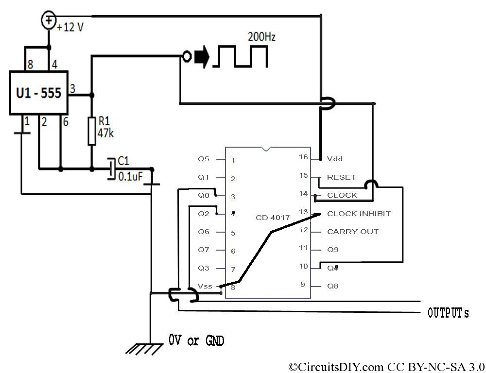
Generating sine waves with controlled frequencies over a wide range is challenging when using RC or LC sinusoidal oscillators. However, this can be effectively achieved using a wideband digital square wave oscillator, a counter, and a weighted summing network....
Simple Surround Sound Decoder. Introduction This surround-sound decoder is based on the Hafler principle, first discovered by David Hafler sometime in the early 1970s. The original idea. The simple surround sound decoder utilizes the Hafler principle to create an immersive...
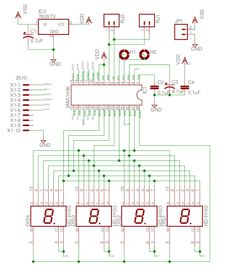
The MAX1496 is an analog-to-digital converter (ADC) that incorporates LED drivers, allowing for the construction of a 3 1/2 digit voltmeter using a minimal number of components. This device features both external and internal voltage reference options, along with...
Most inverters available in the market utilize a modified sine wave to achieve better output at a competitive cost. The modified sine wave unit employs a 50% fixed PWM square wave, with the peaks balanced by a capacitor to...
This circuit is a simple buzzer circuit known as a novel buzzer. It utilizes a relay in series with a small audio transformer and a speaker. The relay will activate the circuit. The novel buzzer circuit operates by employing a...
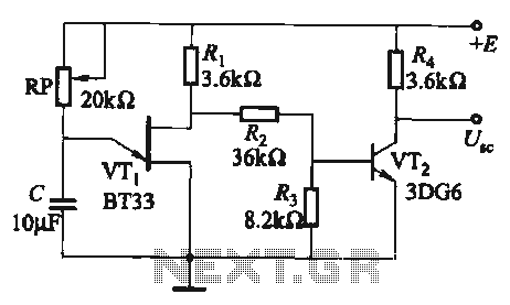
The circuit comprises a single-junction transistor VTi, a resistance Ri, a potentiometer RP, and a capacitor C, forming a relaxation oscillator and an amplifier transistor VTz. The adjustment potentiometer RP allows for changing the relaxation oscillation frequency, providing a...