
simple water level buzzer circuit

The water level buzzer circuit operates on a simple principle of conductivity. Two probes are placed at predetermined levels within the water tank or container. When water bridges the gap between these probes, it completes the circuit. The presence of water lowers the resistance between the probes, allowing current to flow. This current is directed to the base of the NPN transistor, in this case, the BC547B.
In this configuration, the transistor acts as a switch. When the probes are submerged in water, the transistor turns on, allowing current to flow from the collector to the emitter. This current flow activates the buzzer connected to the circuit, producing an audible alert. The use of a variable resistor allows for adjustment of the sensitivity of the probes, enabling the circuit to be tailored for different applications, such as varying water levels in different types of tanks or containers.
The overall design of the circuit is compact and cost-effective, making it suitable for DIY projects and educational purposes. The use of general-purpose transistors ensures that the circuit can be easily replicated using readily available components. Additionally, the low power requirement of the circuit allows it to be powered by a standard 9V battery or a compatible power supply, enhancing its versatility for various applications related to water level monitoring.Here is a simple water level buzzer circuit which can be used to detect or sense the level of water in tank, pool, washing machines etc. When the two probes shown in this water level indicator circuit will detect water the buzzer will start producing sound.
The circuit is very simple and low cost using only few parts like Buzzer, Transistor, 300K variable resistor and a 9V battery or power supply. The circuit is using BC547B NPN transistor but you can use any other general purpose transistor in the place of this transistor like 2N2222 or 2N3904. Working of this water level sensor is simple; the transistor used in the circuit is working as a switch.
When the two probes detect water the transistor becomes switched on and as a result the voltage start passing through the transistor, which will activate the buzzer. 🔗 External reference
Related Circuits
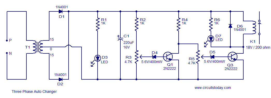
The typical BPM range for music is between 40 and 240 BPM, corresponding to periods of 1500 ms and 200 ms, respectively. A BPM of 120 equates to a period of 500 ms. The circuit requires a resistor R4...
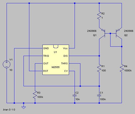
This circuit is a modification of a high and low voltage cut-off with delay and alarm circuit that was featured in Circuits Today. It has been tested and found to be reliable. The circuit can be adapted with minor...
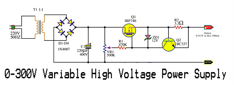
This is a variable high voltage DC power supply circuit that allows for customization of the output voltage ranging from 0 to 311V DC. It includes a current limit protection feature set at approximately 100 mA. The power MOSFET...
The sound of a wah pedal is characterized by a resonant peak in the signal that can be adjusted. In contrast, a notch represents a sudden decrease in level at a specific frequency, which can be advantageous for achieving...
Any PIC microcontroller equipped with an ADC and sufficient memory to accommodate the program can be utilized. An LED is pulsed after each ADC acquisition to indicate the processor's activity, allowing for verification of software functionality. The LCD voltmeter...
This project flashes eight LEDs in an apparently random manner. It uses a 4060 combined counter and display driver IC which is designed for driving 7-segment LED displays. The sequence is not really random because seven of the LEDs...