
Simple Wlen-Bridge Oscillator

The Wien bridge oscillator is a well-known electronic circuit used to generate sine waves. It utilizes a bridge circuit consisting of resistors and capacitors to achieve the necessary phase shift for oscillation. In this particular configuration, the Wien bridge network is responsible for providing a 90-degree phase shift, which is essential for sustained oscillation.
The amplitude of the oscillations is controlled by a lamp, which acts as a variable resistor. As the oscillations increase, the lamp heats up, causing its resistance to rise, which in turn reduces the amplitude of the output signal. This feedback mechanism stabilizes the oscillation amplitude, preventing distortion and ensuring a clean sine wave output. The simplicity of this design, combined with the inherent smoothing effect of the lamp, results in low harmonic distortion—measured at less than 0.3%.
Overall, the circuit is characterized by its effectiveness in producing high-quality sine wave signals, making it suitable for various applications in signal processing and testing. The use of a Wien bridge oscillator with a lamp provides a practical solution for amplitude stabilization while maintaining low distortion levels. In this circuit, the Wen-bridge network provides phase shift, and the lamp regulates the amplitude of the osc illations. The smooth, limiting nature of the lamp"s operation, in combination with its simplicity, gives good results. Harmonic distortion is below 0.3%.
Related Circuits
This project will explain the function of a simple RF field meter. The unit will be in great help to tune transmitters for best performances. At the bottom left corner you will see a voltage divider. This divider is...
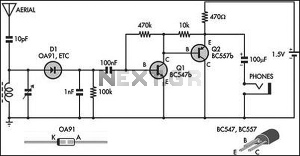
This circuit is an amplified crystal set. The inductor can be a standard AM radio ferrite rod antenna, while the tuning capacitor is a variable plastic dielectric gang designed for small AM radios. The aerial tuned circuit feeds diode...
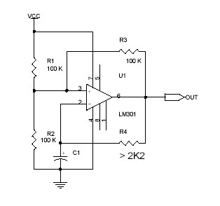
This circuit utilizes the Op-Amp LM301 to generate a simple square wave. The LM301 operates with a power supply range of 3 V to 36 V and can handle a maximum frequency of 325 kHz. The oscillation frequency is...
A DIY GSM jammer schematic diagram designed specifically for GSM1900 frequencies ranging from 1930 MHz to 1990 MHz. The GSM1900 mobile phone network is utilized in the USA, Canada, and most South American countries. This cell phone jammer is...
As a piece of test equipment, an audio oscillator has to be considered essential for anyone working in with hi-fi gear. Together with an audio millivoltmeter (as described in Project 16), and even better if you have access to...
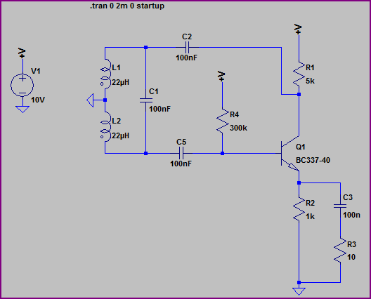
A Hartley Oscillator circuit can be constructed using a pair of series-connected coils. Two 22mH fixed inductors were utilized on a breadboard along with other necessary components. Testing the transistor amplifier independently indicated proper functionality; however, there is no...