
Sine-Wave/Square-Wave Converter

The circuit utilizes an op amp in a comparator configuration, where the op amp's output switches between high and low states based on the input voltage level relative to a reference voltage. In this case, the op amp is designed to produce a 10-V peak-to-peak square wave output, indicating that the output swings from +5 V to -5 V.
The input signal of 100 mV serves as the threshold for the comparator. When the input exceeds this threshold, the output transitions to the high state (approximately +5 V). Conversely, when the input falls below this threshold, the output switches to the low state (approximately -5 V). This behavior allows the circuit to effectively convert a low-level analog signal into a digital square wave.
The frequency response of the circuit is specified to operate up to 15 kHz, which means the op amp can handle input signals with frequencies as high as 15 kHz while still producing a clean square wave output. The performance of the output waveform can be influenced by the values of the surrounding components, particularly the feedback and input resistors.
Resistor R5 plays a crucial role in adjusting the symmetry of the square wave output, especially at low input levels. By varying the resistance of R5, the user can fine-tune the rise and fall times of the output waveform, ensuring that the transitions are balanced and that the duty cycle of the square wave is maintained at the desired level. This adjustment is particularly important in applications where precise timing and waveform characteristics are essential for proper operation.
In summary, this op amp comparator circuit is designed to provide a reliable square wave output from a low-level input signal, with adjustable symmetry to cater to specific application requirements. An op amp used as a comparator produces a 10-V p-p square-wave output with 100-mV input, to 15 kHz. Adjust R5 for symmetry of square wave at low input levels.
Related Circuits

The RS-232 system connection is faster and easier, but the distance is limited. Therefore, this project involves using an RS-485 system with an RS-232 to RS-485 converter. The RS-232 to RS-485 converter project aims to extend the communication range and...
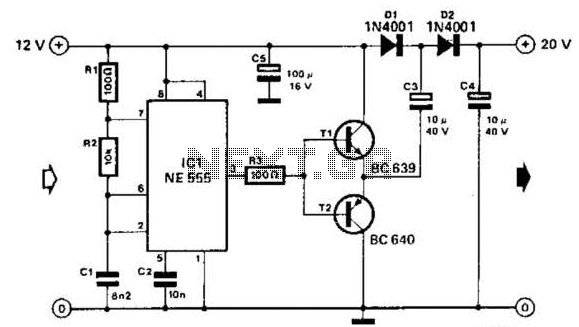
Using a 555 timer and voltage doubler, this circuit will supply over 50 mA at 20 V DC. Transistors T1 and T2 act as power amplifiers to drive the voltage doubler. The frequency of operation is approximately 8.5 kHz. The...
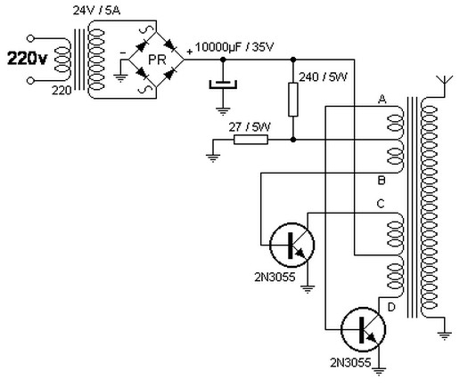
The step-up transformer described can be repurposed as a flyback transformer from an unused television. It is advisable to utilize a basic model without a voltage tripler or high-voltage diode. This type of transformer is capable of generating voltages...

The 24V to 12V converter schematic is straightforward; however, it is important to ensure that all components, including transistors and integrated circuits, are adequately heat dissipated and electrically insulated from metal surfaces. The schematic diagram is derived from the...
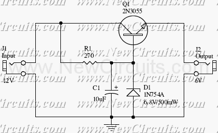
This small but useful circuit is a DC voltage converter for using 6V devices with car battery voltage. The maximum output current is dependent if the T1 is covered with a proper heat sink or not. You can use...
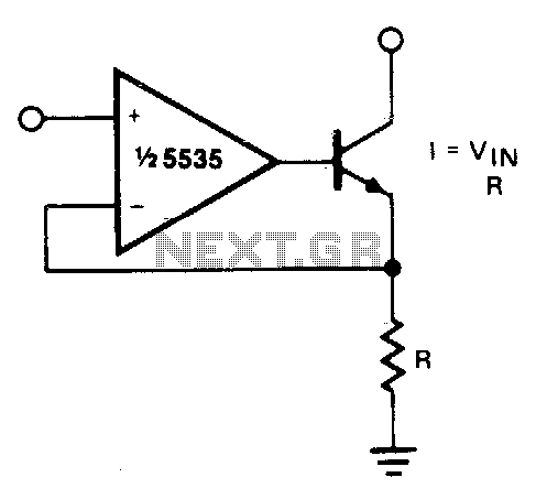
The output current is Iqut = Vin/R. For negative currents, a PNP transistor can be utilized, and for improved accuracy, a Darlington pair may be substituted for the transistor. With careful design, this circuit can be employed to control...