
Single and Two Cell White LED Drivers

The circuit described involves the use of white and ultraviolet LEDs, which typically operate at a voltage range of 2.8 to 4 volts, depending on the specific LED and its current requirements. To drive these LEDs using a 9-volt battery, such as the commonly used 006P transistor radio battery, a current-limiting resistor must be integrated into the circuit. This resistor is essential to ensure that the LEDs operate within their specified current ratings, preventing damage due to excessive current.
The circuit configuration begins with the 9-volt battery connected to the anode of the LED. The cathode of the LED is then connected to one terminal of the resistor, with the other terminal of the resistor connected to the ground. The value of the resistor can be calculated using Ohm’s Law, considering the forward voltage drop of the LED and the desired forward current. For example, if a 4-volt LED is used, and the desired current is 20 mA, the resistor value can be calculated as follows:
R = (V_supply - V_LED) / I_LED
R = (9V - 4V) / 0.02A
R = 250 ohms
A standard resistor value of 220 ohms or 270 ohms could be selected, depending on the closest available standard resistor value. The choice of resistor will slightly affect the brightness of the LED, but it will ensure that the LED operates safely.
In summary, the circuit is designed to efficiently power white and ultraviolet LEDs from a 9-volt battery while maintaining a low cost and ensuring compatibility with battery-operated lanterns. The careful selection of the series resistor is crucial for optimal performance and longevity of the LEDs.The operating voltage of white LEDs coupled with my emotional need for low cost for a given function, motivates me to make LED drivers suitable for battery operated lanterns that can run from a small number of cells. White and Ultraviolet LEDs available at the time of this writing, require higher voltages than colored LED`s.
In the case of the ones I bought most recently, from 2.8 to 4 volts, depending upon operating current and the individual device. A 006P 9 volt transistor radio battery can drive a 4 volt LED quite easily if the correct resistor is placed in series. The 9 volt transistor radio battery is among the most expensive of the common primary batteries, and has a rather low energy capacity,
🔗 External reference
Related Circuits

The circuit utilizes the MAX1576Y charge pump white LED driver, capable of supplying a total current of up to 480mA across two groups (n = 4 white LEDs). Each white LED in the flashing group can draw a maximum...

The circuit depicted in Figure 3-150 involves a contactor (KM1) that releases when the system is shut down. The contactor KM2 is energized, allowing a 220V AC power supply to flow through diodes VD1 and VD2, which serve as...
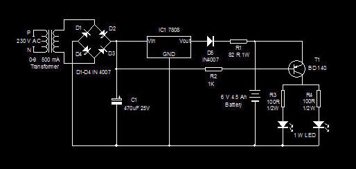
This is a high-efficiency emergency lamp that utilizes high-brightness white LEDs. It automatically activates during power failures and deactivates when power is restored. The emergency lamp circuit is designed to provide reliable illumination during power outages, utilizing high-brightness white LEDs...
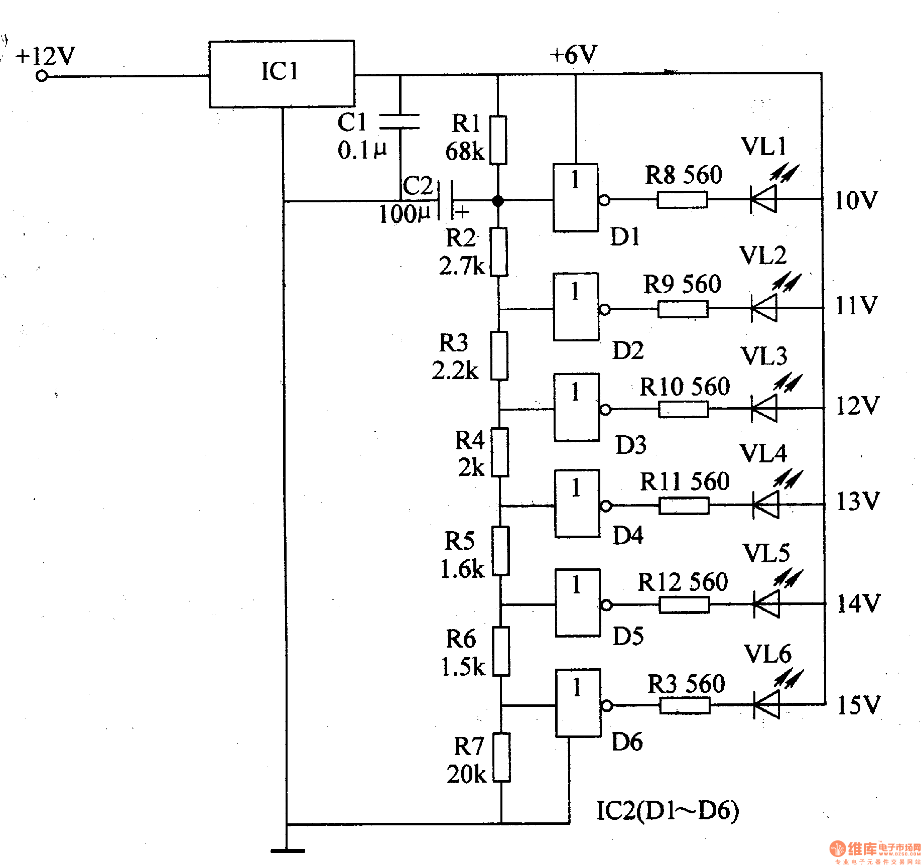
The LED car voltmeter comprises a filter circuit, a voltage distribution filter circuit, a voltage amplifier circuit, and an LED display circuit, as illustrated in Figure 7-77. The regulator filter circuit includes a 3-terminal IC (IC1) and a filter...
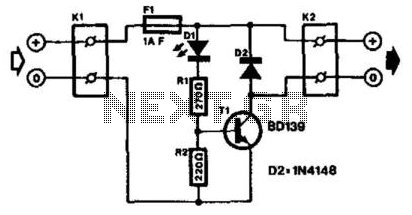
The LED with an integrated flasher is connected in series with the base-emitter junction of transistor T1. Consequently, the load connected to K2 is switched on and off in sync with the flash rate. This load can be a...
This circuit is designed to detect incoming calls on a cellular phone, even when the phone's ringer is turned off, by utilizing a flashing LED. The device should be positioned a few centimeters away from the cellular phone, allowing...