
Single Button Force Sensing Resistor

The FlexiForce sensor is designed to provide precise force measurements in a variety of applications, leveraging its unique resistance properties. The sensor operates on the principle of varying resistance in response to applied force, making it suitable for integration into custom electronic circuits. The calibration process is essential for converting the sensor's output into meaningful engineering units, allowing for accurate force measurement in applications such as robotics, automotive testing, and industrial automation.
In a typical force-to-voltage circuit, the FlexiForce sensor can be paired with operational amplifiers to convert the variable resistance into a voltage output. This configuration often includes a resistor in series with the sensor to form a voltage divider, enabling the measurement of the voltage drop across the sensor as it experiences varying force levels. The output voltage can then be further processed by analog-to-digital converters (ADCs) for digital interfacing with microcontrollers or other processing units.
The construction of the FlexiForce sensors, particularly the A201 and HT201 models, enhances their versatility and durability. The use of flexible printed circuits allows for integration into spaces where traditional sensors may not fit, while the choice of materials ensures performance under various environmental conditions. The male square pins facilitate easy connection to breadboards or custom PCBs, promoting rapid prototyping and development.
Furthermore, the ELF System provides a comprehensive solution for users seeking a complete force measurement setup. This system not only includes the necessary hardware but also the software for data acquisition and analysis, making it suitable for researchers and engineers looking to implement force measurement in their projects without extensive setup time.
Overall, the FlexiForce sensor represents a flexible and effective solution for measuring force in a wide range of applications, offering both ease of integration and reliable performance.The FlexiForce sensor acts as a force sensing resistor in an electrical circuit. When the force sensor is unloaded, its resistance is very high. When a force is applied to the sensor, this resistance decreases. The resistance can be read by connecting a multimeter to the outer two pins, then applying a force to the sensing area. Figure 1 below sho ws both the Force vs. Resistance and Force vs. Conductance (1/R). Note that the conductance curve is linear, and therefore useful in calibration. One way to integrate the FlexiForce sensor into an application is to incorporate it into a force-to-voltage circuit. A means of calibration must then be established to convert the output into the appropriate engineering units.
Depending on the setup, an adjustment could then be done to increase or decrease the sensitivity of the force sensor. Figure 2 below shows a typical sensor response (based on our recommended drive circuit ). We also offer a complete force measurement system. The ELF System is a turnkey package containing force measurement software, electronics, and force sensors.
The FlexiForce force sensor is an ultra-thin, flexible printed circuit. The standard A201 force sensor is constructed of two layers of substrate (polyester) film. The high-temp model (HT201) is constructed of two layers of polyimide. The active sensing area is defined by the silver circle on top of the pressure-sensitive ink. Silver extends from the sensing area to the connectors at the other end of the sensor, forming the conductive leads. A201 sensors are terminated with male square pins, allowing them to be easily incorporated into a circuit.
The two outer pins of the connector are active and the center pin is inactive. FlexiForce Sensors measure force between virtually any two mating surfaces. Below are a few recent examples demonstrating ways customers are using our technology. 🔗 External reference
Related Circuits

This past summer, an inspiration arose from watching "Transformers: Revenge of the Fallen" to construct an enclosure for a vacuum tube amplifier featuring the Decepticon logo. The tube amplifier replaces a solid-state amplifier that was driven by a tube...
Capacitive proximity sensing has gained significant interest among audiences over the past year. At the end of this article, a list of related articles published at Planet Analog is provided for further reading. A simple proximity sensor is designed...
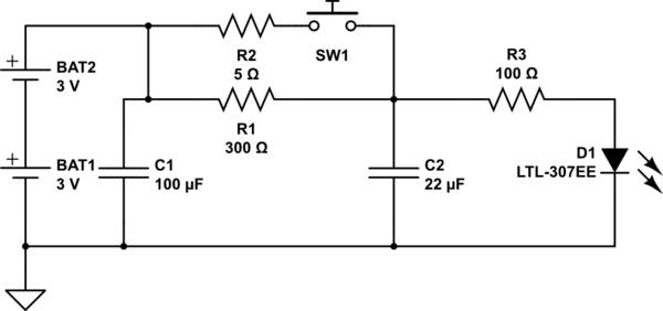
The circuit operates as follows: The LED is typically powered at a low brightness through resistors R1 and R3. SW1 functions as a spring and wire-based accelerometer. When SW1 is activated, capacitor C2 charges rapidly at a rate determined...

Capacitor C1 is charged through timing resistor R1 when the clock output is high. When C1 reaches the upper threshold voltage, the output signal decreases, and then C1 discharges through R1 until its voltage reaches the lower threshold point....
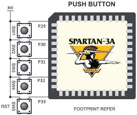
The Spartan-3an board features eight slide switches, as illustrated in the accompanying figure. The push button inputs are typically in a low state and transition to a high state only when the button is pressed. These push buttons are...

The electronic design features a smart battery charger schematic that utilizes only a single transistor. This design is notable as similar circuits typically employ simple integrated circuits. When the battery's charge level falls below a specific threshold voltage, the...