
Single Cell LED Flashlight

The single-cell LED flashlight circuit is designed to provide efficient illumination using a white LED. The circuit operates on a single-cell power source, typically a lithium-ion or alkaline battery, delivering a nominal voltage of around 3.3 V, which is ideal for the forward voltage requirement of the white LED. The LED is selected for its high luminous efficacy, which translates to more light output per unit of power consumed.
To ensure the LED operates at the optimal current of 20 mA, a current-limiting resistor is included in the circuit. The value of this resistor can be calculated using Ohm’s Law, taking into account the supply voltage and the forward voltage drop of the LED. For instance, if the battery voltage is 3.3 V and the LED has a forward voltage of 3.0 V, the resistor value can be determined as follows:
R = (V_supply - V_LED) / I_LED
R = (3.3 V - 3.0 V) / 0.020 A
R = 15 Ohms
Additionally, a switch may be integrated into the design to allow for easy operation of the flashlight. The switch can be placed in series with the battery and LED to control the on/off function.
The circuit design may also incorporate a small PCB (printed circuit board) layout to facilitate compactness and ease of assembly. Proper thermal management should be considered, as excessive current can lead to overheating of the LED, reducing its lifespan.
In summary, this single-cell LED flashlight circuit is a straightforward yet effective design that balances power efficiency and light output, making it suitable for portable lighting applications.This is Single Cell LED Flashlight circuit. This circuit uses white LED that has best power-efficiency combination at about 20mA and requires abut 3.3V. Each.. 🔗 External reference
Related Circuits
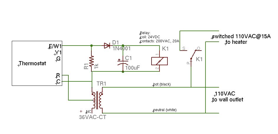
A basic schematic of the circuit is presented, marking the initial experience with Eagle software. It is important to note that only the W1 output of the thermostat is utilized, while C serves as the common connection. The schematic outlines...
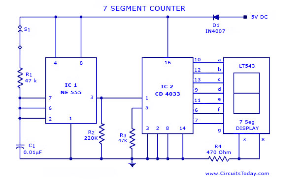
A simple seven-segment counter circuit with an LED display. This counter circuit diagram is designed using the IC CD 4033 as a counter, a 555 Timer IC, and a seven-segment LED display LT 543. The seven-segment counter circuit utilizes the...
For optimal lifespan, it is recommended to operate LEDs at 20-25 milliamps (mA). However, in certain LED flashlight conversions, including many commercial LED flashlights, the LEDs are often driven at 50-60 mA, which is twice the rated current. Testing...
This is a 0 - 6 MHz DDS VFO controlled by a PIC16F84 (or C84). The VFO is separated into two modules, the DDS module and the controller module. The PCB layout (double sided) for the DDS module is...
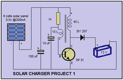
Solar Cell Charger Schematic. The circuit was built with a single oscillator system (blocking oscillator). The solar cell charger schematic utilizes a blocking oscillator configuration to efficiently convert solar energy into electrical energy suitable for charging batteries. This circuit typically...
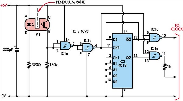
This document outlines the construction of a pendulum-controlled clock designed for high accuracy. Although it has a retro appeal, it represents an intriguing project. The project requires a spare quartz clock, which must be modified by isolating two pads...