
Single-Dc Supply Thermometer

This circuit utilizes a J-type thermocouple, which is capable of measuring a wide temperature range from -350°C to 400°C when powered by a 6-V supply. For applications requiring lower power consumption, the circuit can also operate using a 3-V lithium battery, allowing it to measure temperatures from -50°C to +100°C. The thermoelectric properties of the J-type thermocouple convert thermal energy into a voltage output, which is proportional to the temperature difference between the measurement junction and a reference junction.
The output signal from the thermocouple is fed into the AD954 analog-to-digital converter (ADC). This device is designed to provide a linear output of 10 mV for every degree Celsius of temperature change, thus ensuring high sensitivity and accuracy in temperature readings. The ADC processes the analog signal and converts it into a digital format suitable for further processing.
The digital output from the AD954 is then interfaced with the MAX 138 digital voltmeter chip. This chip is responsible for displaying the converted temperature readings on an LCD display, providing a user-friendly interface for monitoring temperature. The MAX 138 is designed for low power operation, making it suitable for battery-powered applications.
The overall design of this circuit emphasizes efficiency and ease of use, making it ideal for various temperature measurement applications in both industrial and laboratory settings. The choice of components ensures reliable performance, while the LCD display offers clear visibility of temperature readings, facilitating quick assessments and decision-making based on temperature data. Using a J-type thermocouple, this circuit can indicate temperatures from -350° to 400° with a 6-V supply or - 50 to +100° with a 3-V lithium battery. The AD954 produces 10 mV/°C output to the MAX 138 digital voltmeter chip, which drives the LCD display.
Related Circuits
This circuit is a dual voltage regulated power supply, +12, -12, 0 volt. It uses the 7812 and 7912 regulators. You need a 18VCT, 1A transformer at input. More: Caution: Input / Ground are reversed between the 7812 and...
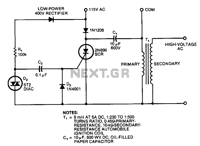
This circuit generates high-voltage pulses using an inexpensive auto ignition coil. By adding a rectifier to the output, the circuit produces high-voltage direct current (DC). The input to the circuit is 115 Vac. During the positive half cycle of...
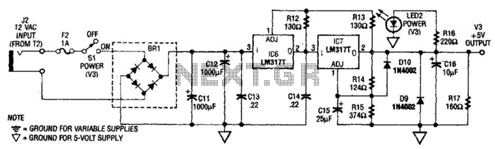
The power supply presented is intended to function with a wall transformer. This circuit can be utilized alongside a variable supply for testing circuits in a laboratory setting. T2 serves as a 12-V wall transformer. The power supply circuit is...
This dual polarity power supply is simple to construct, requires minimal components, and is adjustable from 0 to 15 volts. It is suitable for powering operational amplifier circuits as well as other circuits that necessitate a dual supply voltage....
TR1 provides a constant current to a bank of three zener diodes, thus maintaining a constant voltage independent of supply voltage variations. The resistor Rx is used to sense the PSU output current and to switch off the current...
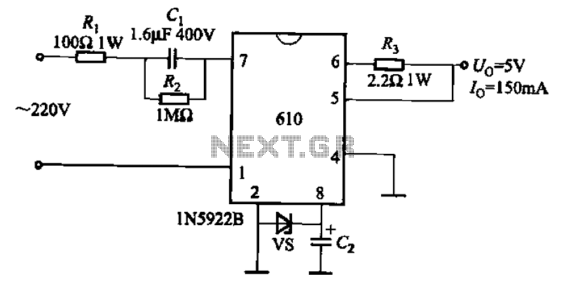
The AX610 Series has a maximum output current of 100 mA and features a scalable output current with an access regulator. The configuration includes two reverse polarity series regulators (2CW106, U: approximately 8.2V) as depicted in Figure (a). Figure...