
SLA7062/67 Step Motor Driver

The SLA7062/67 unipolar driver chip is designed for applications requiring moderate current control, making it suitable for various automation and motion control projects. The chip's ability to provide up to 3 amps is particularly beneficial for driving motors or actuators in CNC machinery, robotics, and other electromechanical systems.
The circuit schematic typically includes the SLA7062/67 connected to a power supply that meets the voltage requirements of the chip. The input control signals are routed to the chip's control pins, which dictate the operation of the output stage. The inclusion of a 10-pin IDC connector (PMinMO) facilitates easy interfacing with other components, such as microcontrollers or motion control systems, ensuring a seamless integration into existing setups.
The PCB layout designed for the SLA7062/67 should consider thermal management and component placement to minimize noise and interference. Proper decoupling capacitors should be placed near the power supply pins to stabilize the voltage levels and filter out high-frequency noise. Additionally, the BOM will list all necessary components, including resistors, capacitors, and any additional drivers or protection diodes required for optimal performance.
For users looking to implement this driver in their projects, sourcing the SLA7062/67 chips from alternative suppliers may be necessary if stock is unavailable at Newark (Farnell). BatchPCB provides a reliable option for obtaining custom PCBs, allowing for flexibility in design modifications as needed. Overall, the SLA7062/67 chip, paired with the appropriate PCB and components, offers a robust solution for driving applications in various electronic systems.The SLA7062/67 chip is a unipolar driver and can provide up to 3amps. The chip is hard to find and will cost about $10. each. Using Google, I found the three that I needed for my prototypes. Newark (Farnell) sells them but has no stock. The pcb`s can be purchased from Batchpcb and below find the BOM and the circuit diagram. This board uses the 10 pin IDC connector (PMinMO) and is compatible with the CNC USB Motion Controller. 🔗 External reference
Related Circuits
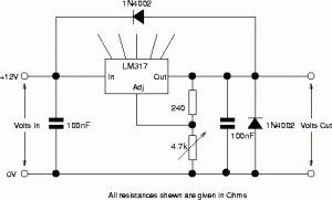
The following circuit illustrates the circuit diagram of a motor control unit. This circuit is based on the LM317 integrated circuit. Features include diodes that protect the regulator. The motor control unit circuit utilizes the LM317 voltage regulator to provide...
This DC Motor Controller circuit will control a 12V dc motor. The system will have three pushbuttons: a START button, a REVERSE button and a STOP button. Initially, the motor must not be running. When the START button is...

The purpose of this circuit is to maintain a permanent magnet DC motor at a constant speed, which is set externally. This is achieved by monitoring the current flowing through and the voltage across the motor's brushes. The schematic for...
Assistance is required for a final year project involving the design of a grid-connected inverter. The focus is on developing a full bridge inverter circuit. The grid-connected inverter is a crucial component in renewable energy systems, particularly in solar photovoltaic...
A four thyristor controlled bridge is utilized for operation in two quadrants of the torque-speed characteristics. In the trigger circuits, conventional pulse transformers are substituted with self-biased circuits, which reduce gate power consumption and enhance noise immunity. Electrical isolation...
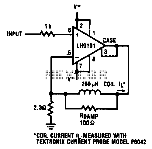
A 500 mV peak-to-peak triangular waveform centered around ground is applied to the amplifier, resulting in a peak current of 100 mA flowing through the inductor. The circuit involves an amplifier configured to process a triangular waveform signal with a...