
Control circuit keeps dc motor running at constant speed

The schematic for this circuit typically includes a feedback loop that incorporates a speed sensor, such as a tachometer, which provides real-time feedback on the motor's speed. The output from the tachometer is compared to a reference voltage that corresponds to the desired speed setting. This comparison is usually performed using an operational amplifier configured as a differential amplifier.
The output of the operational amplifier is then used to control a PWM (Pulse Width Modulation) signal that drives a power transistor or MOSFET. This transistor acts as a switch to control the voltage applied to the motor. By adjusting the duty cycle of the PWM signal, the effective voltage and current supplied to the motor can be varied, thus controlling its speed.
Additional components may include a current sensing resistor placed in series with the motor, allowing for the measurement of the motor's current. This current feedback can be used to implement current limiting or protection features to prevent damage to the motor during stall conditions or overload situations.
Filtering capacitors may also be included in the circuit to smooth out any voltage spikes or noise, ensuring stable operation. Diodes are typically placed in parallel with the motor to protect against back EMF generated when the motor is turned off or when it operates under dynamic conditions.
Overall, this circuit design effectively ensures that the DC motor operates at the desired speed, providing reliable performance in various applications where speed control is critical.The aim of this circuit is to keep the permanent magnet dc motor running at a constant speed, set externally. To do this, the current through, and the voltage across, the brushes of the motor are monitored 🔗 External reference
Related Circuits
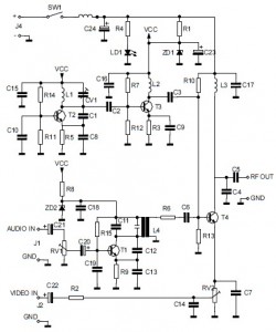
This is the circuit diagram of an audio/video modulator. The circuit converts audio and video signals into a UHF TV signal. It is designed to connect a video signal originating from a camera or other video source to a...
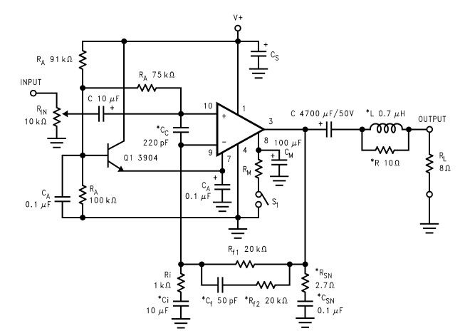
The LM2876 audio power amplifier circuit can be designed as a simple, high-efficiency audio amplifier capable of delivering 40W of continuous average power to an 8-ohm load with a total harmonic distortion plus noise (THD+N) of 0.1% from 20Hz...
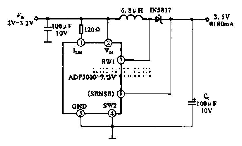
Boost 3.5V regulator circuit. This chip can boost or create a stable voltage supply from approximately 3V DC to a DC voltage of 3.5V. The boost regulator circuit is designed to increase a lower DC voltage, specifically from around 3V...
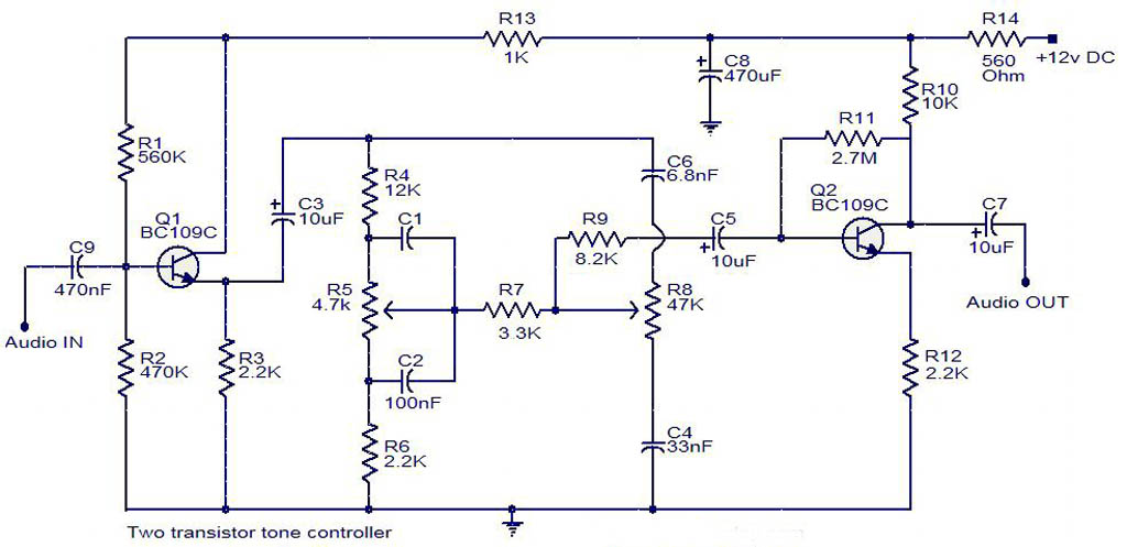
The electrical schematic diagram presented below illustrates a simple two-transistor tone controller audio circuit, which is available for free download. This circuit is based on the well-known Baxandall tone control design. Variations in the values of the transistor components...
A servo controller has evolved from a "servo slower" unit, designed to reduce the slew rate (traverse time) of proportional servos. In model boats, this device is commonly used to control the rotation of a servo-driven gun turret, as...
The topic of alternative keyboard layouts has gained traction due to advancements in Software and MIDI technology, making it practical to explore different configurations. This post aims to clarify what alternative keyboard layouts are, distinct from other methods of...