
SING AROUND COUNTER CONTROL

The timer start-pulse generator circuit employs a series of transistors configured to achieve a high-speed coincidence detection. In this configuration, the transistors are arranged to process input signals and generate a precise timing pulse that initiates the operation of subsequent stages in the system. The use of a fast series-transistor arrangement ensures minimal delay, allowing for accurate timing in applications that require rapid signal processing.
The slope-gate generator functions as a one-shot multivibrator, which is crucial for managing the control of the 1N97A diode. This diode plays a vital role in blocking unwanted negative sync pulses generated by the blocking oscillator. The multivibrator is designed to trigger only under specific conditions, thereby preventing erroneous signal transmission that could compromise measurement accuracy.
In the context of ultrasonic velocity measurements, the circuit counts sing-around cycles, which are essential for determining the time it takes for ultrasonic waves to travel through a medium. This measurement is critical for applications in both liquids and solids, where precise velocity data is necessary for various industrial and scientific purposes. By integrating this timer start-pulse generator with other components in an ultrasonic measurement system, it enhances the overall performance and reliability of velocity assessments, ensuring that the data collected is both accurate and repeatable.Timer start-pulse generator is fast series-transistor coincidence circuit. Slop-gate generator is one-shot mvbr that prevents 1N97A diode from passing blocking oscillator negative sync pulse until mvbr fires. Used to count number of sing-around cycles and measure total time in system for measuring ultrasonic velocity in liquids and solids.
-R. L. F orgacs, Precision Ultrasonic Velocity Measurements, Electronics, 33:47, p 98-100. 🔗 External reference
Related Circuits
This circuit provides an explanation of the Phase-Locked Loop (PLL) controller unit for an FM transmitter. It is crucial for maintaining a digitally controlled and stable transmitter frequency. The core component of this unit is a PIC processor, specifically...
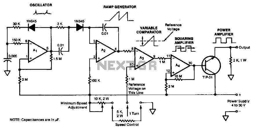
The quad operational amplifier circuit provides a pulse width modulation control ranging from 0 to 100 percent. The controller utilizes an LM3900 and operates with a single supply voltage between 4 to 30 V. A 1 kHz oscillator amplifier,...
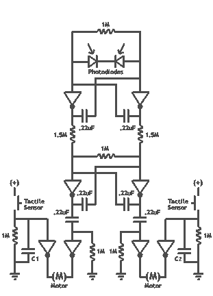
It's basically a photovore with a couple tactile sensors. It's rather complex but can give neat behaviors with modifications to the circuit. At this point I don't have any plans to give more information on this circuit so your...
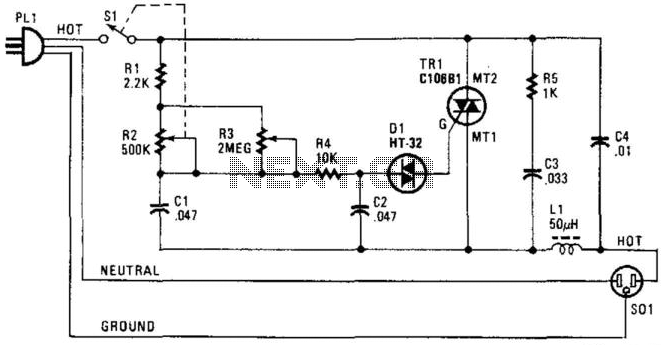
A phase-controlled triac (HT-32) circuit offers control over the effective voltage at the load. It is important to include LI and C4, as they are essential for RFI suppression. The maximum load capacity is approximately 500 W. WARNING: 120...
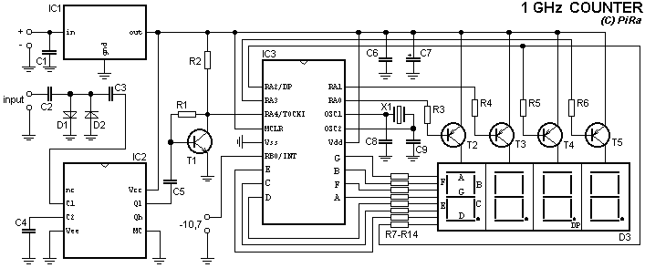
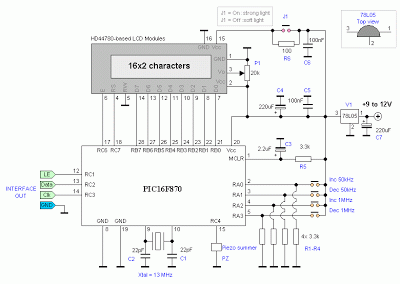
This very simple counter can be used to measure the frequency of various wireless devices. Applies in reviving the transmitter and its operation as a control monitor frequency. It can be used as a scale to the receiver. Due...
The circuit consists of a delay loop, discriminators, output circuits, power supply, and indicator lights, divided into five parts. The power regulation is achieved through a resistor (R), while the power regulator is constructed using a voltage source. In...