
Small 3-wheel ROBOT with PIC16F84 brain & InfraRed eyes

The circuit involves an infrared LED that emits light at a frequency of 36 kHz. This light travels until it encounters an object, where it is reflected back towards a photodetector or infrared receiver module. The photodetector is designed to be sensitive to the 36 kHz frequency, ensuring that it only activates in response to the reflected infrared light.
Upon receiving the reflected signal, the receiver module sends a signal to the PIC16F84 microcontroller. This microcontroller is programmed to interpret the input from the receiver module. In response to the signal, the microcontroller executes a control algorithm that determines the appropriate action for the robot. Specifically, it will reverse one of the motors to steer the robot away from the detected obstacle.
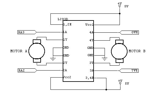
The circuit may also include additional components such as resistors for current limiting, capacitors for signal smoothing, and possibly a transistor or relay to control the motor's operation. The motor driver circuit is crucial as it interfaces between the microcontroller and the motors, allowing the low-power signals from the PIC16F84 to control the higher power requirements of the motors.
Overall, this design exemplifies a basic obstacle avoidance mechanism in robotic applications, utilizing infrared sensing technology and microcontroller logic to achieve autonomous navigation.When the 36 kHz infrared light from the LEDs is reflected by an object, one of the receiver modules will be triggered, and the PIC16F84 µController will steer the ROBOT away from the objects by reversing one of the motors. 🔗 External reference
Related Circuits

To enable a line-following robot to identify the line, it is essential to first detect the line itself. Several methods can be employed to distinguish a black line on a white background, or vice versa. One effective approach is...
This is the circuit diagram of a line follower/line tracker robot. The circuit is derived from tutorial documentation, which can be downloaded at the end of this article. The line follower robot utilizes eight proximity sensor modules. Each sensor...
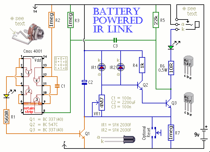
This is a battery-powered infrared (IR) link that can be utilized in multiple rooms. The standby current is exceptionally low, resulting in excellent battery life. The circuit is designed to shut down when faced with extraneous IR radiation, effectively...
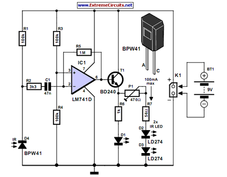
Many consumer electronic devices such as television sets, VCRs, CD players, and DVD players utilize infrared remote control technology. In certain situations, it is beneficial to extend the range of these remote controls. Infrared (IR) remote controls operate by emitting...
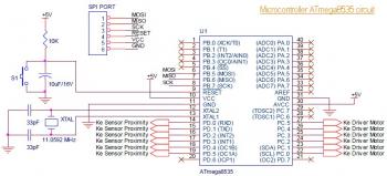
The robot consists of modules controlled by a main controller. The main microcontroller is an 18-pin, 8-bit PIC16F84 Flash microcontroller operating at 4MHz. The microcontroller is programmed in assembly language. The controller is connected via I/O pins to the...
R2 sets the output voltage. The maximum current is determined by the value of R3: the over-current protection circuitry inside the LM723 senses the voltage across R3 and starts shutting the output stage off as soon as this voltage...