
smart phone light circuit diagram

The first section of the circuit operates as a ring detector. When the telephone is on-hook, approximately 48V DC is present across the TIP and RING terminals. During this state, the diode in the opto-coupler remains off, drawing negligible current from the telephone lines. The opto-coupler also provides isolation from the phone lines. The transistor within the opto-coupler is typically off, with a +5V signal present at the ring indicator line. When the phone rings, an AC voltage of about 70-80V AC is present across the telephone lines, activating the diode inside the opto-coupler (IC2) and subsequently turning on the transistor within the opto-coupler. This causes the voltage at its collector to drop to 0V during the ringing, triggering IC3, a 74LS123(A) monostable flip-flop.
The second opto-coupler (IC1) monitors the ambient light conditions. Under sufficient light, the LDR exhibits a low resistance of around 5 kilo-ohms, keeping the transistor in the opto-coupler in the on state. Conversely, when light levels are inadequate, the LDR's resistance rises to several mega-ohms, switching the transistor to the off state. As a result, the DC voltage at the collector of the transistor in the opto-coupler typically remains at 0V, rising to 5V when light is insufficient.
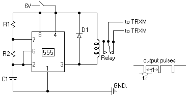
The 74LS123 retriggerable monostable multivibrator generates a programmable pulse width. The first monostable 74LS123(A) produces a pulse from the trigger input during ringing, provided that its pin 2 input (marked B) is at a logic high (i.e., during darkness). The output remains high for a predetermined duration before returning to 0V. The high-to-low transition at the trailing edge triggers the second monostable flip-flop 74LS123(B) within the same package. The output from the second monostable controls a relay, activating the lamp through the normally open (N/O) contacts of the relay. The duration for which the lamp remains on can be extended by pressing pushbutton switch S1. If the phone is not answered, the light will automatically turn off after a specific time period corresponding to the pulse width of the second flip-flop.
The light sensitivity of the LDR can be adjusted by changing the resistance R2 connected to the collector of the transistor in the light monitoring circuit. Additionally, the duration for which the lamp is activated can be controlled by varying the capacitance value of capacitor C3 in the second 74LS123(B) monostable circuit.The circuit shown here is used to switch on a lamp when the tele- phone rings, if the ambient light is insufficient. The circuit uses only two ICs and it can be implemented very easily. A light dependent resistance (LDR), with about 5 kilo-ohms resistance in the ambient light and greather than 100 kilo-ohms in darkness, is at the heart of the circ
uit. The circuit is fully isolated from the phone lines and it draws current only when the phone rings. The circuit provides automatic switching on of a lamp during darkness when the phone is kept in a place such as the bedroom. The lamp can be battery powered to provide light during power failure or load shedding. This avoids delay in attending to a call. The light switches off automatically after a programmable time period and it needs no attention at all.
If required, the lamp lighting period can be extended by simply pressing a pushbutton switch (S1). The first part of the circuit functions as a ring detector. When telephone is on-hook, around 48V DC is present across the TIP and RING terminals. The diode in the opto-coupler is off during this condition and it draws practically no current from he telephone lines. The opto-coupler also isolates the circuit from the telephone lines. Transistor in the opto-coupler is normally off and a voltage of +5V is present at the ring indicator line.
When telephone rings, an AC voltage of around 70-80V AC, which is present across the telephone lines, is used to turn on the diode inside the opto-coupler (IC2) which in turn switches on transistor inside the opto-coupler. The voltage at its collector passes through 0-volt level during ringing to trigger IC3 74LS123(A) monostable flip-flop.
The other opto-coupler (IC1) is used to detect the ambient light condition. When there is sufficient light, LDR has a low resistance of about 5 kilo-ohms and the transistor inside the opto-coupler is in on state. When there is insufficient light available, the resistance of LDR increases to a few mega-ohms and the transistor switches to off state.
Thus the DC voltage present at the collector of transistor inside the opto-coupler is normally 0V and it jumps to 5V when there is no light or insufficient light. The 74LS123 retriggerable monostable multivibrator is used to generate a programmable pulse-width. The first monostable 74LS123(A) generates a pulse from the trigger input available during ringing, provided its pin 2 input (marked B) is logic high (i.
e. during darkness). It remains high for the programmed duration and switches back to 0V at the end of the pulse period. This high-to-low transition (trailing edge) is used to trigger the second monostable flip-flop 74LS123(B) in the same package. Output of the second monostable is used to control a relay. The lamp being controlled via the N/O contacts of the relay gets switched on. The on period can be extended by simply pressing pushbutton switch S1. If nobody attends the phone, the light turns off automatically after the specific time period equal to the pulse-width of the second flip-flop.
The light sensitivity of LDR can be changed by changing resistance R2 connected at collector of the transistor in light monitor circuit. Similarly, switch-on period of the lamp can be controlled by changing capacitor C3 s value in the second 74123(B) monostable circuit Disclaimer: All the information present on this site are for personal use only.
No commercial use is permitted without the prior permission from authors of this website. All content on this site is provided as is and without any guarantee on any kind, implied or otherwise. We cannot be held responsible for any errors, omissions, or damages arising out of use of information available on this web site.
The content in this site may contain COPYRIGHTED information and should not be reproduced in any way without prior permission from the authors. 🔗 External reference
Related Circuits
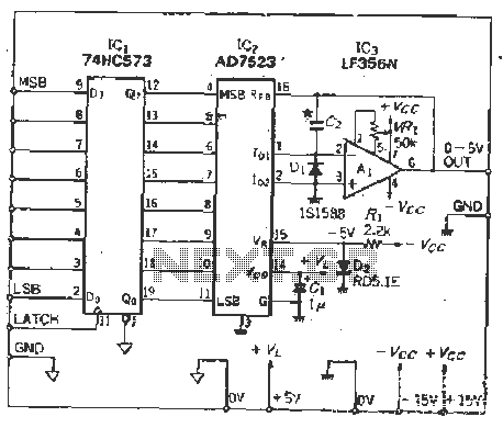
The IC latch is utilized to hold the digital data when the clock signal rises. The configuration includes a holding data port AD7s23, a thin film resistor ladder, and a switch that together form an 8-bit Digital-to-Analog Converter (DAC)....

It consists of a 4047 low-power monostable/astable multivibrator, IC1, used in the astable mode to provide the timing pulses to control the flash rate of the LEDs. To accomplish the astable mode, pins 4, 5, 6, and 14 are...

The 1-megohm resistor protects the FET from potential damage caused by accidental sparks to its gate lead. The circuit functions adequately without this resistor; however, it is advised not to intentionally apply a charge to the gate wire using...

The precision Phase Locked Loop (PLL) in this circuit operates similarly to a basic PLL, but with several enhancements. The flip-flops in the detector are equipped with a gate G1 to clear them, allowing for a faster response. The...
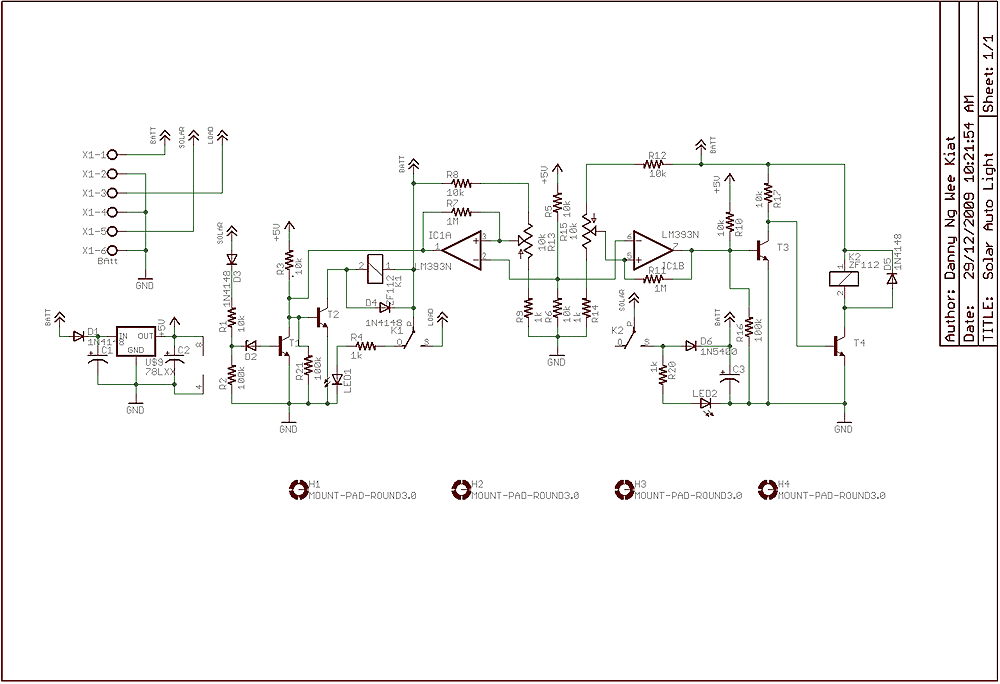
Few years back, I had been working on a project for solar auto lighting. The light will turn on when the solar panel voltage drop below a set point indicating that it is dark. The detection is done by...
This webpage outlines the radio transmitter unit that was part of the Cirrus One rocket mission in April 2001. The transmitter was included as a payload due to concerns about recovery challenges if the rocket drifted far downrange after...