
SMOKE DETECTOR USING 555 TIMER

The smoke sensing alarm circuit operates based on the interaction between the photo interrupter module and the NE555 timer. The photo interrupter module consists of an infrared LED and a phototransistor, which work in tandem to detect the presence of smoke. Under normal conditions, the LED emits light that is detected by the phototransistor, keeping the collector terminal low. This low signal is necessary to keep the reset pin of the NE555 timer low, preventing the timer from oscillating.
When smoke enters the detection area, it scatters or absorbs the light emitted by the LED, preventing it from reaching the phototransistor. As a result, the phototransistor's collector voltage rises towards the supply voltage, sending a high signal to the reset pin of the NE555 timer. This transition triggers the timer to start oscillating, producing a square wave output at a frequency of approximately 379 Hz.
The output from the NE555 timer is connected to a loudspeaker through a coupling capacitor, which allows the AC signal to drive the speaker while blocking any DC component. The resulting sound from the loudspeaker serves as an alarm, alerting individuals to the presence of smoke. The choice of a frequency around 379 Hz is intentional, as it is within the audible range and is easily recognizable as an alarm sound.
Overall, this smoke sensing alarm circuit is a practical application of the NE555 timer in conjunction with a photo interrupter module, effectively providing an early warning system for smoke detection. The simplicity of the design makes it accessible for various applications, from home safety systems to educational projects in electronics.I am presenting you a simple smoke sensing alarm circuit using 555 timer. By using this circuit you can detect smoke and it alarms when the air is contaminated. Let me introduce you the components used in it. This smoke detecting alarm is based directly on an astable multivibrator and sensor (Photo interrupter module). The sensing module trig gers the oscillator and generates an alarm through the loud speaker. The photo interrupter module consists of an LED and a Photo transistor. The light coming from the led falls directly onto the photo transistor, this makes the collector terminal to go ground potential and activates the reset control of 555 timer. If there is an interrupt on the path of LED and Photo transistor as smoke, the light doesn`t reaches the transistor causing the collector voltage approximately equal to supply voltage and it is fed directly to the reset pin of NE555, which is wired as astable multivibrator.
The high voltage at this pin enables the ic and it produce square waves continuously, which in turn drives the speaker through a coupling capacitor. Here the astable multivibrator is configured as AF oscillator with a frequency of 379Hz, so as to hear the alarm through Loud speaker.
🔗 External reference
Related Circuits

This circuit is capable of sensing eight colors: blue, green, and red (primary colors); magenta, yellow, and cyan (secondary colors); along with black and white. It is designed based on the principles of optics and digital electronics. The object...
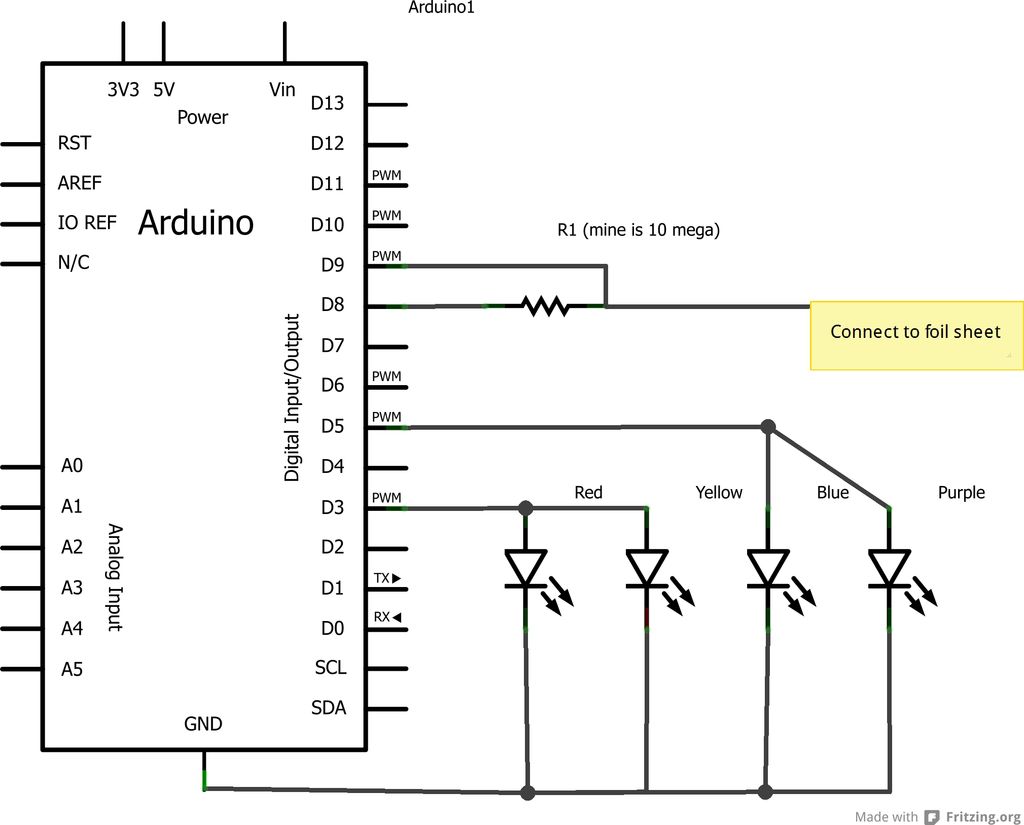
This project is an Arduino-based light control system that is ideal for beginners. It allows the fading of colors or lights by detecting hand movements nearby. The system transitions from a purple-blue hue to a fiery red-orange. The assembly...

The difference between instantaneous frequency and central frequency of the carrier is directly proportional to the instantaneous value of the amplitude of the message signal. A 555 Timer configured in Astable Mode can be utilized for generating Frequency Modulated...
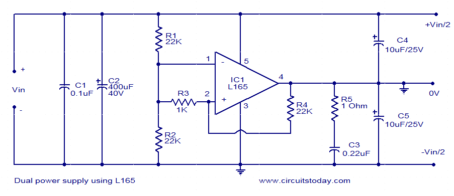
This dual power supply utilizes the L165 power operational amplifier from SGS-Thomson Microelectronics. The L165 IC can deliver up to 3.5A of current, with internal current limiting. It is available in a Pentawatt package, making it well-suited for power...

This circuit features an adjustable output timer capable of re-triggering at specified intervals. The output duration can range from a fraction of a second to over half an hour, with the ability to recur at regular intervals spanning from...
The TDA 2030, produced by SGS Ates, is a complete audio amplifier. It is a Class AB amplifier capable of delivering 14 watts into a 4-ohm load with a power supply of ±14V. By connecting two TDA2030 amplifiers through...