
Soft ON/OFF switch circuit

The described circuit utilizes a JK flip-flop configured as a toggle flip-flop, which is integral for the ON/OFF functionality of the equipment. The JK flip-flop is a bistable multivibrator capable of holding two stable states, which correspond to the ON and OFF states of the device. In this configuration, both the J and K inputs are connected to a high logic level (logic '1'), allowing the flip-flop to toggle its output state with each clock pulse.
The clock signal is generated by the push button switch that serves as the ON/OFF control. When the button is pressed, it momentarily connects the clock input of the flip-flop to a high state, causing the flip-flop to change its output state. This toggling mechanism allows the equipment to remain in its last state until the button is pressed again, creating a user-friendly interface.
To ensure reliable operation, the circuit includes a resistor-capacitor (RC) debounce network connected to the push button switch. This configuration prevents false triggering of the flip-flop due to mechanical bouncing of the switch contacts when pressed. The capacitor charges and discharges through the resistor, smoothing out the transitions and providing a clean clock signal to the flip-flop.
Additionally, the circuit incorporates a RESET button, which allows the user to force the flip-flop into a known state (OFF) regardless of its previous state. This feature is particularly useful for initializing the device or for troubleshooting purposes.
The output of the JK flip-flop can be connected to a relay, which controls the power to the equipment. The relay's state will correspond to the flip-flop's output, thus enabling or disabling the power supply to the device. The design ensures that the relay can be in either state (ON or OFF) when the circuit is powered on, providing flexibility in operation.
This circuit design exemplifies modern electronic control systems that utilize silent push-to-on-push-to-off switches, enhancing user experience while maintaining functionality similar to traditional mechanical switches.When the "ON/OFF" button is pressed once, the equipment goes on and stays on. It goes off when the button is pressed again. The circuit is straight forward. It uses a JK CMOS FlipFlop to with its JK terminals tied high to achieve the toggling action. The clock is provided by the push button used for on/off action. The resistor and the capacitor near the on/off switch debounces the contacts. Note that when the circuit is switched on, the relay may land in a on or off state. It can be brought to the off state by pressing the RESET button. Modern electronic equipment incorporate "push-to-on-push-to-off" switches that do not make the clicking noise as with old equipment. An example of this is the power button on a ATX computer cabinet. Here is a circuit that does the same. It can b 🔗 External reference
Related Circuits
In spite of the improvement of communication link and despite all progress in advanced communication technologies, there are still very few functioning commercial wireless monitoring systems, which are most off-line, and there are still a number of issues to...
Here is a simple circuit which can be used for decoration purposes or as an indicator. Flashing or dancing speed of LEDs can be adjusted and various dancing patterns of lights can be formed. The circuit consists of two...
The Adjustable Timer circuit initiates timing upon activation. A green LED illuminates to indicate that timing is in progress. Once the designated time period elapses, the green LED turns off, the red LED activates, and an audible bleeper sounds....
This article presents basic circuits for pulsing infrared LEDs and low-power visible semiconductor lasers utilizing inexpensive and readily available components. Numerous interesting and practical applications are referenced, alongside several online resources. The focus of the article is on the...
This document outlines a straightforward process to transmit voice over a distance using amplitude modulation of light through sound vibrations. It details how modulated light is detected and demodulated by a receiver to reproduce sound. The experiments described are...
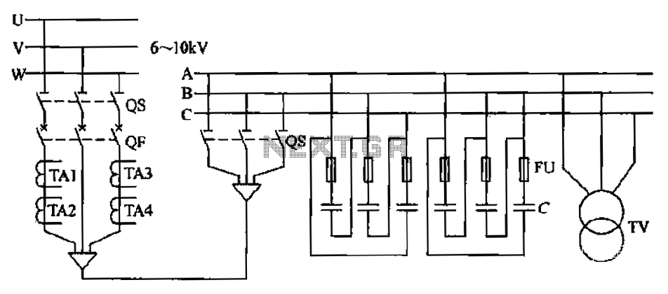
The compensation system is designed to focus on a high-pressure, high-voltage capacitor bank installed in the substation 6-10 kV bus. Compensation can only be implemented in this manner for the 6-10 kV bus before the reactive power on the...