
light beam circuit

The described circuit involves a transmitter and a receiver, where the transmitter consists of a tube with an aluminum foil diaphragm at one end. When a voice is spoken into the tube, sound waves travel down the length of the tube, causing the diaphragm to vibrate. This vibration alters the angle of the light reflected from the diaphragm, resulting in amplitude modulation of the light beam. The light beam, when directed towards a receiver, carries the modulated information.
The receiver is equipped with a light detector, which may be a photodiode or a phototransistor, that captures the modulated light. The detector converts the light variations into an electrical signal, which is then amplified using an operational amplifier (op-amp) circuit. The output of the op-amp is connected to a speaker, which acts as a transducer, converting the amplified electrical signal back into audible sound.
To optimize the system, it is crucial to ensure that the transmitter is positioned to receive direct sunlight, and the receiver is aligned to capture the reflected light effectively. The use of different materials for the diaphragm, such as shiny gift wrapping foil or mirrors, can enhance the efficiency of the modulation process. The dimensions of the tube can also be varied to determine the best performance for the specific setup being utilized.
This project not only serves as an engaging experiment but also provides insight into fundamental concepts of amplitude modulation, light transmission, and sound reproduction, making it an excellent educational tool for understanding basic principles of electronics and communication systems.Here we describe a simple process to `put a voice on a sunbeam` and transmit it over a distance. It is a fascinating example of amplitude modulation of light using sound vibrations. We then describe how the modulated light is detected and demodulated in a receiver so that we can hear the sound. A wide range of physics and engineering experience ca n be learnt through these exciting `sunbeam` experiments. These activities are inexpensive and can be made in a school laboratory or at home. The interconnected computers forming the Information Super Highway (the Internet) depend on the ability to encode and decode information (e. g. a voice, picture or program) on the communication network. This network might be thousands of miles of wires, fibre optics, under sea cables or use satellites. Although this `information` may appear in an identical from on the distant computer there must be a large amount of encoding / decoding along the way, to make it all happen reliably.
The process of encoding information for transmission is called modulation and the subsequent information retrieval is called demodulation. On a computer system a `black box` does this job at either end of the network and is called a Modem (short for Modulator / Demodulator).
With other types of information communication, for example in radio broadcasts, the modulation of the programme is done at the transmitter and the demodulation performed within the radio receiver. In the following article however, we look at a more simple system which uses a most basic modulation / demodulation process called amplitude modulation.
We will learn about this process in an exciting and entertaining way. Bright sunlight (a sunbeam) will be modulated to carry voice information. Then, after sending it over a distance, we will demodulate it to be able to hear the sound. The experiments described here were one of the challenges for the popular BBC2 / Open University TV series - Rough Science - and the series were first transmitted in the UK in January 2004. In these experiments Sunlight strikes an aluminium foil diaphragm (or mirror, see `transmitter` section below) covering the end of a tube.
When you talk into the tube the sound waves travel down causing the foil to vibrate. The light hitting the foil would normally reflect off at an angle. But now additional constantly changing deviations in angle, take place which dependant on the amplitude and frequency of the foil diaphragm vibrations. At some distance away the reflected spot of light may appear slightly fuzzy instead of sharp because of this `modulation` movement.
If you take a small part of the spot its amplitude will vary over time. It will vary in exactly the same manor as the vibration of the foil due to the voice sound waves. The reflected light beam has therefore been amplitude modulated by the sound. If we arrange for a light detector to receive some of this modulated light its electrical output will vary (because of the amplitude modulation) in an identical way to that caused by the voice. When this is amplified and fed to a speaker (a transducer that converts electricity to sound) we hear the original sound once more!
In practice you need to arrange the transmitter reflector so that it receives a good source of direct sunlight and of course the receiver needs to be able to clearly see the reflection but it is really as simple as this! This is an open tube made from plastic, cardboard or metal having dimensions between 1-10cm diameter and 10-50cm long.
One end has a thin layer of aluminium foil taped over it. In practice all sorts of diameters and lengths need to be tried to find the most efficient for your set-up. You might also try other reflecting surfaces for the diaphragm, such as shinny gift wrapping foil, a mirror fixed to a rubber sheet etc.
The detector does the very important job of converting the light into electricity. The signal then needs to be amp 🔗 External reference
Related Circuits
A bandpass filter allows a specific range of frequencies to pass while rejecting frequencies that fall outside the upper and lower limits of the passband. The frequencies that are permitted to pass are referred to as the passband, which...

A simple remote control tester circuit with a diagram and schematic using the infrared sensor IC TSOP1738. An LED will blink when infrared waves fall on it, indicating the remote control is functioning. The remote control tester circuit utilizes the...
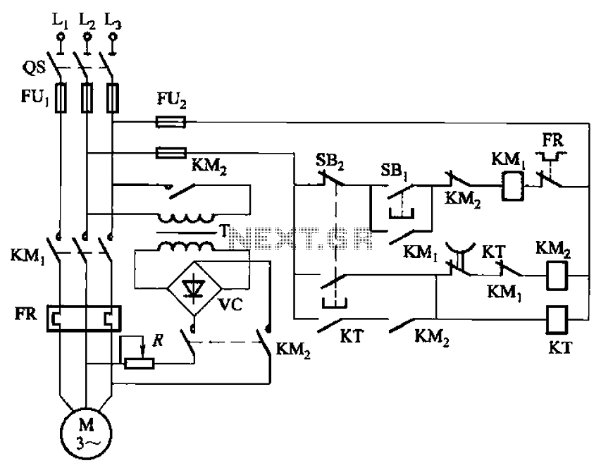
The circuit depicted in Figure 3-135 employs a time relay (KT) to determine the braking time. The circuit utilizes a time relay, which is a crucial component for controlling the duration of the braking process. The time relay KT is...
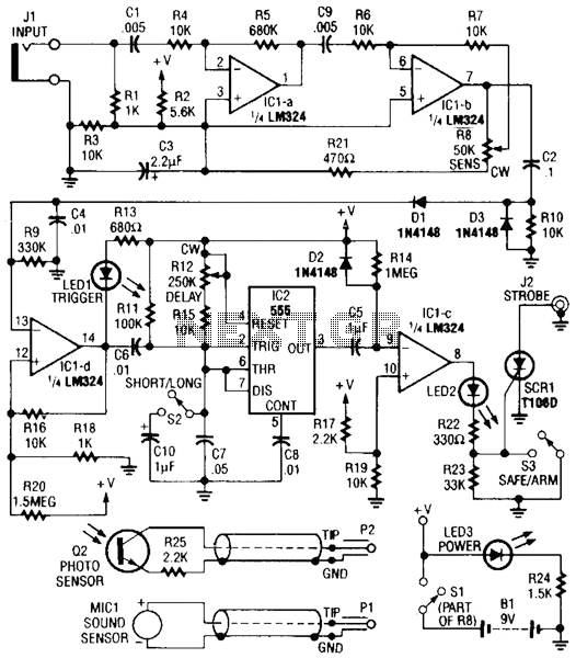
Sound or light sensors connected to J2 produce a voltage that is amplified by IC1-a and IC1-b. A positive trigger voltage developed by D1 and R3, and amplified by IC1-d, drives IC2 and IC1 to trigger SCR1. SCR1 is...

This circuit is a simple DC to DC converter designed for digital circuits. It operates with a supply voltage of 5V and provides an output voltage that steps up to a maximum of 10V-12V DC. The circuit utilizes an...

TDA7262 stereo 20 watts audio amplifier circuit design electronic project The TDA7262 is an integrated circuit designed for stereo audio amplification, capable of delivering up to 20 watts per channel. This amplifier circuit is suitable for various applications, including home...