
SOIL MOISTURE METER

The circuit utilizes the Intersil ICL7106 integrated circuit, which serves as the core component for analog-to-digital conversion and display functionality. The ICL7106 is designed to drive an LCD, providing a clear digital readout of the measurements taken by the probe. The inclusion of a clock and voltage reference within the IC ensures stable operation and accurate conversions.
The probe's design, using lightweight aluminum tubing, enhances portability and ease of use while maintaining structural integrity. The variable resistor sensor is critical for the measurement process, as it directly influences the base current of Q1, a transistor that acts as an amplifier. The collector current of Q1, which is modulated by the sensor's resistance, is then translated into a voltage signal across resistor R7. This voltage is fed into the ICL7106, which converts the analog signal into a digital format for display.
Power consumption is a key consideration in the design, with the LCD operating at a low current draw of around 25 microamperes, and the ICL7106 drawing less than 2 milliamperes. This efficient power management allows the device to be powered by a 9-volt battery or two 1.5-volt AA cells, both of which provide sufficient energy for extended use without frequent battery replacements.
Calibration is a straightforward process, involving the adjustment of potentiometers R3 and R8 to ensure accurate readings. By setting R3 to the center position and immersing the probe in water, the user can calibrate the device to read a standard value of 100. Subsequent adjustments ensure that the device accurately returns to a reading of 000 when removed from the water, confirming the reliability of the sensor and the associated circuitry. This calibration procedure is essential for maintaining measurement accuracy in practical applications.IC1, an Intersil ICL7106, contains an a/d converter, a 3 1/2-digit LCD driver, a clock, a voltage refer-ence, seven segment decoders, and display drivers. A similar part, the ICL7107, can be used to drive seven segment LEDs. The probe body is a five-inch length of light-weight aluminum tubing. The leads from the circuit are connected to the body a nd tip of the probe. The sensor functions as a variable resistor that varies Q1`s base current, hence its collector current. The varying collector current produces a varying voltage across 100 © resistor R7, and that voltage is what IC1 converts for display.
The LCD consumes about 25 A, and IC1 consumes under 2 mA, so the circuit will run for a long time when it is powered by a standard 9-V battery. Current drain of the two 1. 5-V AA cells is also very low: under 300 A. To calibrate, rotate R3 to the center of its range. Then place the end of the probe into a glass of water and adjust R8 for a reading of 100. When you remove the probe from the water, the LCD should indicate 000. You might have to adjust R3 slightly for the display to indicate 000. If so, readjust R8 with the probe immersed. Check for a reading of 000 again with probe out of water. 🔗 External reference
Related Circuits
The MCU is an ATMEL 89C4051 CMOS Microcontroller featuring 4kB of code memory, 128 bytes of on-chip RAM, and 8-bit Port1 and Port3. The A/D chip is a HARRIS CA3162, which functions as a 3-digit digital voltmeter (DVM). This...
The concept for this circuit was developed due to issues experienced with a bicycle's wireless speedometer. This device comprises two components: the cycle computer and a transmitter mounted on the front fork. A small magnet is affixed to the...
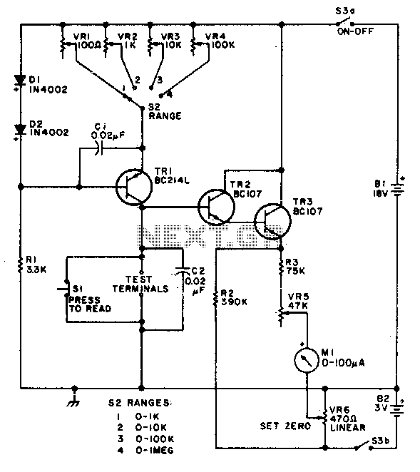
This circuit is designed to provide accurate measurement and a linear resistance scale at the high end. The circuit has four ranges. Additionally, another meter with a current range of 10 µA to 10 mA and a sensitivity of...
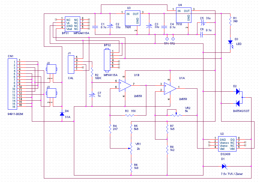
The resolution of the barometric pressure is approximately 0.00417 inHg (0.0139 kPa) within a pressure range of 31.0 to 28.0 inHg (105.0 to 95.0 kPa, or 1050 to 950 mb or hPa). Higher resolutions can be achieved with a...
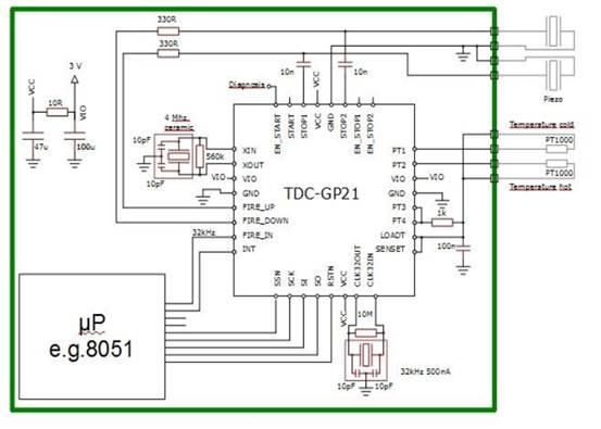
Enhancements include an analog front end, pin-to-pin compatibility for existing designs, an analog stabilized comparator, and simplified external circuit design. There is improved time and temperature measurement with reduced current consumption. The TDC-GP21 is ideally suited for designing compact...

This circuit is designed to provide an affordable method for creating a high impedance voltmeter using a low-cost analog or digital multimeter. The circuit is specifically intended for testing phototransistors. When measuring voltages in high resistance circuits, the resistance...