
Solar Based Multipurpose Charger Circuit

The solar energy harvesting circuit is designed to facilitate the efficient charging of multiple battery types through the conversion of solar energy into electrical energy via a 12-volt, 5-watt solar panel. The solar panel consists of photovoltaic cells made from semiconductor materials, which generate an output voltage of around 16.5 volts at optimal sunlight conditions, providing a sufficient current of 400 mA for charging applications.
The circuit employs a diode (D1) to manage the flow of current into three voltage regulator integrated circuits (ICs). The first regulator, IC1 (7812), is responsible for providing a stable 12-volt output suitable for charging lead-acid batteries. The connection for the lead-acid battery is made at point C, with the negative terminal grounded.
For charging nickel-cadmium (NiCd) batteries, the circuit utilizes the second regulator, IC2 (7806), which outputs a regulated 6 volts. A current-limiting resistor (R3) is incorporated into the design to prevent excessive charging current that could damage the battery.
The third regulator, IC3 (7805), supplies a regulated output of 5 volts, which is ideal for charging mobile phone batteries rated at 3.6 volts. To ensure safe charging, resistor R2 is used to limit the current flowing to the mobile phone batteries.
Additionally, point A on the circuit can be utilized for charging lithium-ion and nickel-metal hydride (NiMH) batteries, providing versatility in battery charging options.
To enhance the reliability of the charging process, high-value capacitors (C1 and C2) are included in the design. These capacitors act as current buffers, ensuring that any transient interruptions in the solar panel's output do not adversely affect the charging operation.
Finally, a red LED indicator is integrated into the circuit to provide a visual cue of the charging status, allowing users to easily monitor the operation of the charger. This comprehensive solar energy harvesting circuit design effectively addresses the need for a multi-purpose battery charger while ensuring safety and reliability in its operation.An ideal solution to harvest Solar energy for charging purpose. This charger can replenish almost all types of batteries including Mobile phone battery. It uses a Solar Module to convert light energy into electrical energy The circuit is self explanatory. A 12 volt 5 Watt solar panel is used as the source of current. The cells in the panel are made up of semiconductor material which transforms light energy into electrical energy. When the sunlight is maximum, the solar module can generate around 16. 5 volts at 400 mA. This current is used to charge the battery. Diode D1 allows current into three regulator ICs to provide regulated voltage to the load. IC1 7812 gives 12 volts and 400 mA current to charge a Lead Acid battery. The battery can be connected to point C and ground. IC2 7806 gives regulated 6 volts to charge NiCd battery. Resistor R3 restricts the charging current. IC3 7805 provides regulated 5 volts to charge all types of Mobile phone batteries which are rated at 3. 6 volts. Resistor R2 restricts charging current to a safer level. Point A can also used to charge Lithium ion and NiMh batteries. High value capacitors C1 and C2 act as current buffers so that a short duration interruption in current flow from the panel will not affect the charging process.
Red LED indicates the charging process. 🔗 External reference
Related Circuits
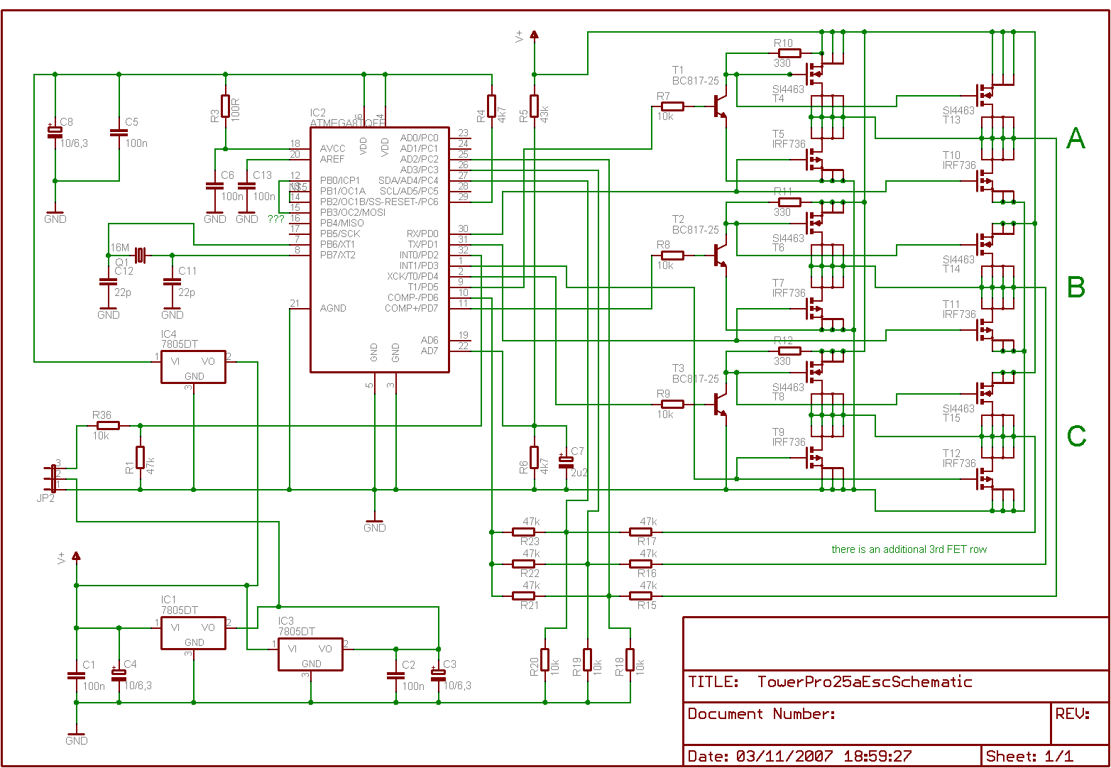
Is it feasible to eliminate the Electronic Speed Controllers (ESCs) from a multicopter configuration and substitute them with a single circuit board to control all the motors? The current setup consists of eight motors, each requiring an individual ESC,...
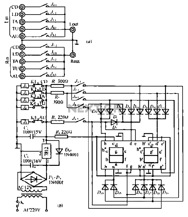
Can simulate the character Mu symbol. A bone dish SET code is needed that effectively manages the decimal point. An inverted J is required to open its mouth. Left foot circuit diagram. The project involves designing a circuit that simulates...
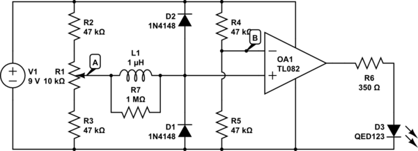
The circuit above is a canonical AC coupled common emitter amplifier, which is typically used as a linear amplifier rather than a switch that activates when the input exceeds a certain level. The AC coupled common emitter amplifier is...
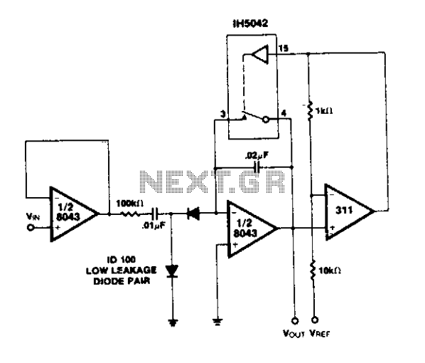
A simple circuit utilizing an LM311 as a level detector and a CMOS analog gate for capacitor discharge is presented. A notable feature of this counter type is the ease of changing the count, which only requires adjusting the...
This circuit is a simple IR detector for testing IR remote controllers. The circuit is based on one phototransistor which receives the IR beam. The NPN transistor works as an amplifier which feeds current to the LED. When this...
This circuit is beneficial for applications where a load must be activated from one location and deactivated from another. Multiple momentary normally open (N/O) switches or push buttons can be connected in parallel. The circuit described facilitates remote control of...