
Solar Panel Based Charger And Small LED Lamp

The described circuit demonstrates a versatile solar charging system capable of supporting various battery types, enhancing energy efficiency and sustainability. The inclusion of protection diodes ensures safe operation, while the use of specific components like the 7806 and 7805 regulator ICs allows for controlled charging currents suited to the different battery chemistries. The design also emphasizes the importance of monitoring battery health, particularly for lead-acid batteries, and provides a practical solution for integrating LED lighting with renewable energy sources. The overall assembly is designed for ease of use and accessibility, making it suitable for various applications in renewable energy and portable power solutions.You can save on your electricity bills by switching to alternative sources of power. The photovoltaic module or solar panel described here is capable of delivering a power of 5 watts. At full sunlight, the solar panel outputs 16. 5V. It can deliver a current of 300-350 mA. Using it you can charge three types of batteries: lead acid, Ni-Cd and Li-io n. The lead-acid batteries are commonly used in emergency lamps and UPS. The working of the circuit is simple. The output of the solar panel is fed via diode 1N5402 (D1), which acts as a polarity guard and protects the solar panel. An ammeter is connected in series between diode D1 and fuse to measure the current flowing during charging of the batteries.
As shown in Fig. 1, we have used an analogue multimeter in 500mA range. Diode D2 is used for protection against reverse polarity in case of wrong connection of the lead-acid battery. When you connect wrong polarity, the fuse will blow up. For charging a lead-acid battery, shift switch S1 to on` position and use connector A. ` After you connect the battery, charging starts from the solar panel via diode D1, multimeter and fuse.
Note that pulsating DC is the best for charging lead-acid batteries. If you use this circuit for charging a lead-acid battery, replace it with a normal pulsating DC charger once a week. Keep checking the water level of the lead-acid battery. Pure DC voltage normally leads to deposition of sulphur on the plates of lead-acid batteries. For charging Ni-Cd cells, shift switches S1 and S3 to on` position and use connector B. ` Regulator IC 7806 (IC1) is wired as a constant-current source and its output is taken from the middle terminal (normally grounded).
Using this circuit, a constant current goes to Ni-Cd cell for charging. A total of four 1. 2V cells are used here. Resistor R2 limits the charging current. For charging Li-ion battery (used in mobile phones), shift switches S1 and S2 to on` position and use connector C. ` Regulator IC 7805 (IC2) provides 5V for charging the Li-ion battery. Using this circuit, you can charge a 3. 6V Li-ion cell very easily. Resistor R3 limits the charging current. Fig. 2 shows the circuit for a small LED-based lamp. It is simple and low-cost. Six 10mm white LEDs (LED2 through LED7) are used here. Just connect them in parallel and drive directly by a 3. 6V DC source. You can use either pencil-type Ni-Cd batteries or rechargeable batteries as the power source. Assemble the circuit on a general-purpose PCB and enclose in a small box. Mount RCA socket on the front panel of the box and wire RCA plug with cable for connecting the battery and LED-based lamp to the charger.
🔗 External reference
Related Circuits
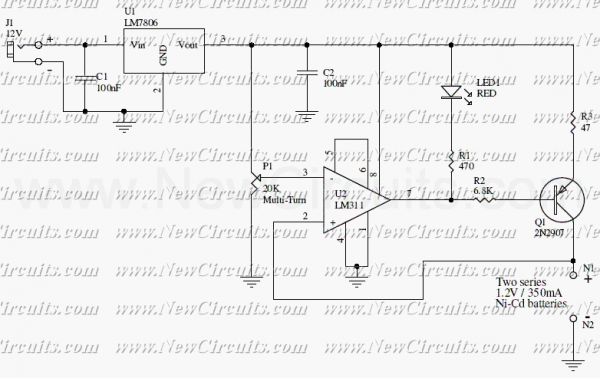
The circuit presented in the above schematic has been designed to charge automatically two series 350mAh "AAA" size batteries. Set the 20KOhms multiturn potentiometer to get a 2.78V on the 3rd pin of the LM311 which is a comparator....

This article discusses a simple 5-channel radio remote control circuit utilizing the TX-2B and RX-2B integrated circuits from Silan Semiconductors. The TX-2B/RX-2B is a remote encoder-decoder pair suitable for remote control applications. It features five channels, a wide operating...
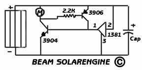
Well the most common use is in a solaroller which is a small wheeled car that charges up and then moves in a quick burst of speed. Since you can only use motors and coils with this circuit robots...
Almost any 2x16 character LCD module with Hitachi HD44780 controller chip will work. The LCD pin numbers on the schematic are not valid for all LCD modules. Please check the actual signal names on your particular LCD module. The...
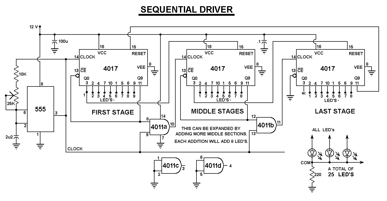
All LED negatives are connected to the "COM" pad, then through a 220 Ohm resistor to ground. There is no need for additional current limiting resistors, even with supply voltages up to 16 volts. The described circuit employs a simple...
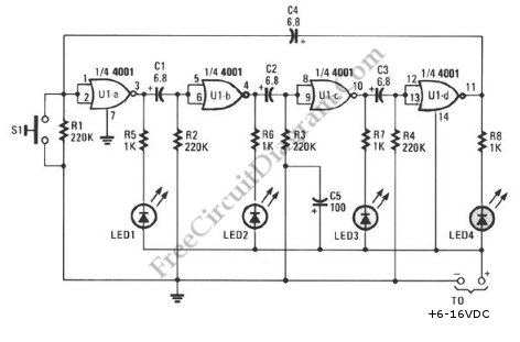
This schematic diagram illustrates a ring-around LED flasher circuit. The circuit operates by turning off two LEDs while activating the other two, continuing this pattern until the timing cycle reverses. The ring-around LED flasher circuit is designed to create a visually...