
Ring-Around LED Flasher

The ring-around LED flasher circuit is designed to create a visually appealing light effect by alternating the illumination of two pairs of LEDs. The circuit typically consists of a microcontroller or a timer IC that generates a control signal to manage the timing of the LEDs.
In a standard configuration, two LEDs are connected in series with current-limiting resistors to ensure that they operate within their specified voltage and current ratings. The microcontroller or timer IC is programmed to activate the first pair of LEDs while simultaneously deactivating the second pair. After a predetermined interval, the states of the LEDs are reversed, resulting in a continuous flashing effect.
The timing cycle can be adjusted by changing the values of the timing components, such as resistors and capacitors, associated with the timer IC or microcontroller. This allows customization of the speed at which the LEDs alternate, providing flexibility for different applications.
Power supply considerations must also be addressed, ensuring that the circuit operates within the voltage range suitable for the selected LEDs and control components. Additionally, the use of a breadboard or PCB can facilitate prototyping and assembly, allowing for easy modifications and testing of the circuit design.
Overall, the ring-around LED flasher circuit is an effective way to create dynamic lighting displays, suitable for decorative purposes, signaling, or as part of larger electronic projects.This schematic diagram shows a ring-around LED flasher circuit. This circuit will turn off two LEDs and turn on the other two until the timing cycle reverses 🔗 External reference
Related Circuits
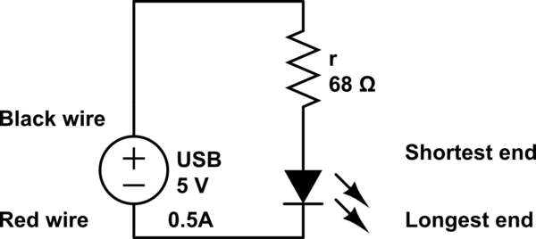
The LED operates at 3V, and based on information available online, a blue LED typically supports a maximum current of 0.03A. Given the available current from the USB source, the intention is to construct a parallel circuit. However, the...

In this application, a BA1404 is utilized to generate an FM MPX baseband signal. This signal modulates a crystal oscillator (Q3) through a dual varactor series modulator. This transmitter can be used to play CD audio on an existing...

A simple LED voltmeter is designed to monitor the charge level in a lead-acid battery or tubular battery. The terminal voltage of the battery is displayed using four LED indicators. The nominal terminal voltage for a lead-acid battery is...
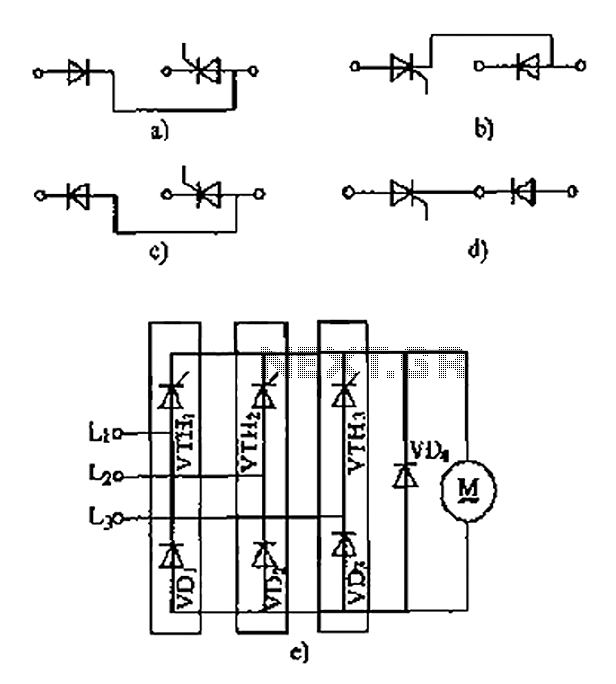
The thyristor linking arm rectifier module is a three-phase half-controlled bridge rectifier circuit. The thyristor-rectifier module linking arm consists of a thyristor and a rectifier diode connected in series or parallel, designed to fulfill specific requirements in power circuits....
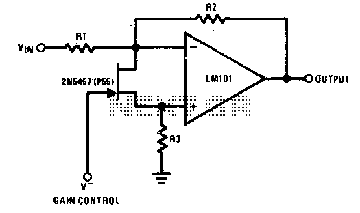
The 2N5457 functions as a voltage-variable resistor with a maximum RdS of 800 ohms. Given that the differential voltage on the LM101 is in the low millivolt range, the 2N5457 JFET exhibits linear resistance over several decades, offering excellent...
This circuit provides a visual 9-second delay using 10 LEDs before closing a 12-volt relay. When the reset switch is closed, the 4017 decade counter is reset to the 0 count, illuminating the LED driven from pin 3. The...