
Solar Powered High Efficiency Charger

This circuit design utilizes a solar-powered NiCd battery charger that operates with high efficiency and flexibility. The solar cells convert sunlight into electrical energy, which is then managed by the MAX639 regulator. The regulator's unique operation mode allows it to maintain optimal charging conditions by adjusting the input voltage rather than the output voltage, a departure from conventional designs. The use of a potential divider to manipulate the voltage feedback and low battery input signals ensures that the system can efficiently respond to varying solar conditions and battery states.
The integration of a step-down regulator is crucial for adapting to different battery pack configurations, allowing for a wide range of terminal voltages. The current limiting feature of the MAX639 prevents potential damage to the battery cells by capping the output current at 200 mA, which is suitable for charging up to five NiCd cells in series. The internal switch within the regulator, characterized by a minimal resistance, facilitates efficient power transfer with minimal energy loss, contributing to the overall performance of the charger.
The choice of using twelve amorphous solar cells, each with a significant surface area, ensures sufficient power generation even under less-than-ideal lighting conditions. The circuit’s design also emphasizes low quiescent current, which enhances the overall efficiency of the charger, making it a viable solution for off-grid applications or situations where solar energy is the primary power source. The 100 µH suppressor choke, rated for 600 mA, is an essential component that helps filter out unwanted noise and stabilize the current, further enhancing the reliability of the charging process. Overall, this solar-powered NiCd battery charger represents an innovative approach to renewable energy utilization, combining efficiency, adaptability, and practicality.This is a simple NiCd battery charger powered by solar cells. A solar cell panel or an array of solar cells can charge a battery at more than 80 % efficiency provided the available voltage exceeds the fully charged` battery voltage by the drop across one diode, which is simply inserted between the solar cell array and the battery. Adding a step-do wn regulator enables a solar cell array to charge battery packs with various terminal voltages at optimum rates and with efficiencies approaching those of the regulator itself. However, the IC must then operate in an unorthodox fashion (a. k. a. Elektor mode`) regulating the flow of charge current in such a way that the solar array output voltage remains near the level required for peak power transfer.
Here, the MAX639 regulates its input voltage instead of its output voltage as is more customary (but less interesting). The input voltage is supplied by twelve amorphous solar cells with a minimum surface area of 100 cm2.
Returning to the circuit, potential divider R2/R3 disables the internal regulating loop by holding the V-FB (voltage feedback) terminal low, while divider R1/R2+R3 enables LBI (low battery input) to sense a decrease in the solar array output voltage. The resulting deviation from the solar cells` peak output power causes LBO (low battery output) to pull SHDN (shutdown) low and consequently disable the chip.
LBI then senses a rising input voltage, LBO goes high and the pulsating control maintains maximum power transfer to the NiCd cells. Current limiting inside the MAX639 creates a ceiling` of 200 mA for I out. Up to five NiCd cells may be connected in series to the charger output. When on` the regulator chip passes current from pin 6 to pin 5 through an internal switch representing a resistance of less than 1 ohm.
Benefiting from the regulator`s low quiescent current (10 microamps typical) and high efficiency (85 %), the circuit can deliver four times more power than the single-diode configuration usually found in simple solar chargers. Coil L1 is a 100- µH suppressor choke rated for 600 mA. 🔗 External reference
Related Circuits
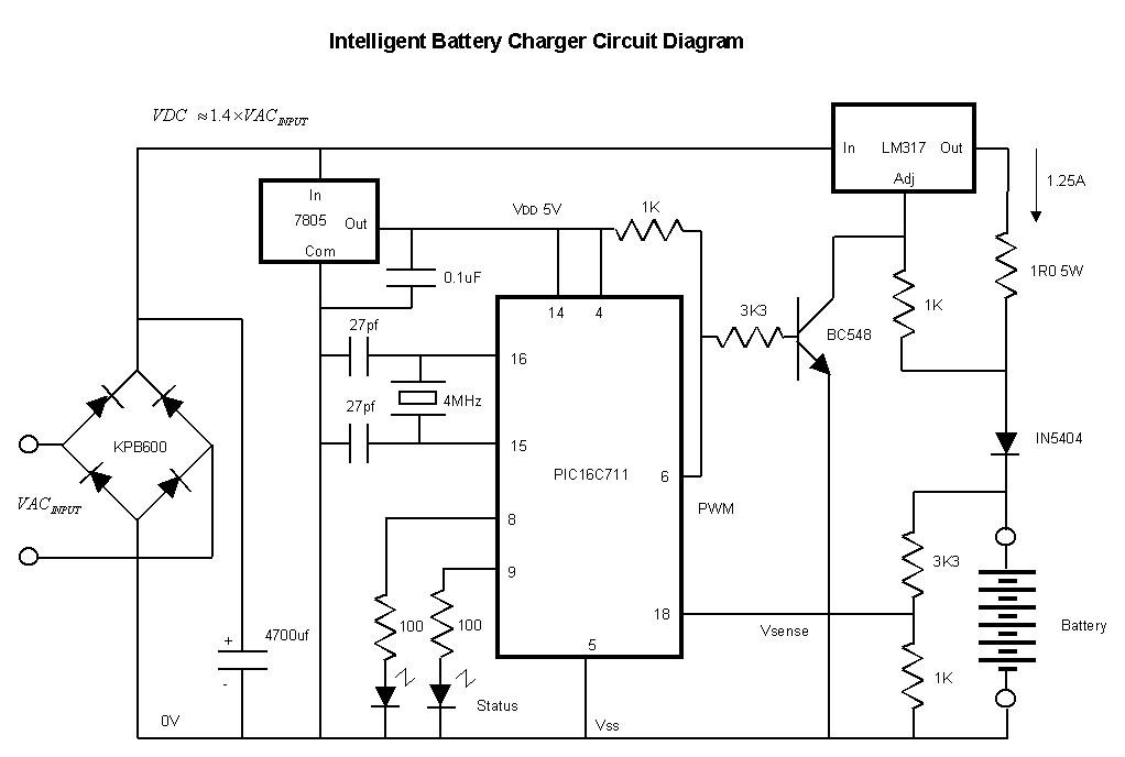
The charger is built around a LM317 adjustable regulator. The charge starts when a battery is connected between pins JP1-JP4 or JP2-JP4 or JP3-JP4. For example, if a battery is connected to JP1-JP4 pins then the current that flows...
The prototype was successfully assembled on a breadboard and subsequently built on a piece of Radio Shack protoboard for field use. The assembly process took only a couple of hours, and it functioned correctly on the first attempt. This...
This affordable and simple-to-construct NiCd/NiMH battery charger is designed for the automatic charging of various batteries used in numerous applications. Reliable chargers are typically costly, while inexpensive chargers that come with original equipment often fail to charge cells correctly,...
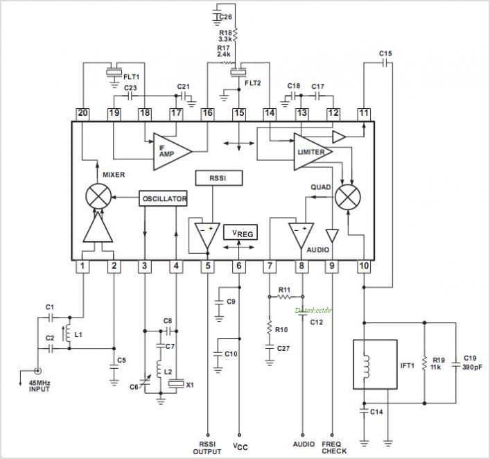
The SA608 is a low-voltage, high-performance monolithic FM intermediate frequency (IF) system that includes a mixer, oscillator, two limiting intermediate frequency amplifiers, a quadrature detector, a logarithmic received signal strength indicator (RSSI), a voltage regulator, and audio and RSSI...
The circuit provides sufficient illumination suitable for reading purposes. Capacitor CX, in conjunction with diodes D1 through D4, constitutes the AC step-down circuit. CX lowers the high voltage AC from the mains to a low voltage AC, which is...
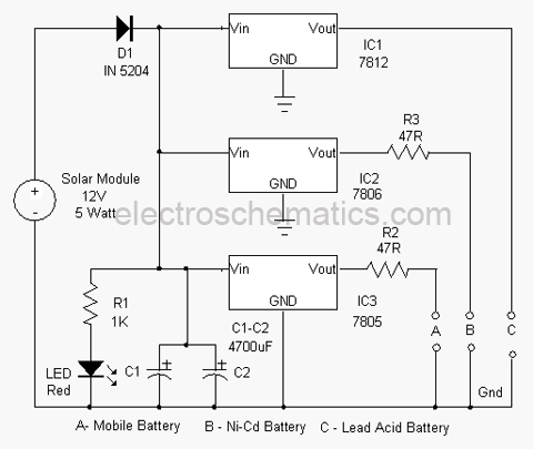
An effective solution for harvesting solar energy for charging purposes. This charger can replenish almost all types of batteries, including mobile phone batteries. It utilizes a solar module to convert light energy into electrical energy. The circuit is self-explanatory....