
Solar powered robot

The schematic for the solar-powered robot utilizes several fundamental electronic components, each playing a critical role in the functionality of the circuit. The primary components include two types of transistors (2N3904 and 2N3906), a 4700 µF capacitor, a 2.2V flashing green LED, a 2.2 kilo-ohm resistor, and one or more solar cells.
The solar cells, ideally sourced from calculators, serve as the energy source for the robot. When exposed to light, these cells generate a small voltage which is not sufficient to power the motor directly but can be used to charge the capacitor. To enhance the energy output, multiple solar cells can be connected in parallel, ensuring that the positive terminals are interconnected while the negative terminals are also joined. This arrangement increases the overall current available for charging.
The capacitor acts as a storage unit for the energy harvested from the solar cells. The 4700 µF capacitor is selected for its ability to hold a significant charge, allowing the circuit to deliver bursts of energy to the motor. When the voltage across the capacitor reaches a certain threshold, it discharges rapidly, providing enough energy to activate the motor momentarily.
The motor, which can be sourced from devices like Walkmans, is connected to the output of the capacitor. The transistors (2N3904 and 2N3906) are used to control the flow of current from the capacitor to the motor, acting as switches that can be activated when the capacitor is sufficiently charged. The 2.2 kilo-ohm resistor is utilized to limit the current flowing into the base of the transistors, preventing damage and ensuring proper operation.
When the assembled robot is placed under a light source, it begins to charge the capacitor. After a few seconds of charging, the capacitor releases its stored energy, causing the motor to spin and the LED to flash. This cycle can repeat as long as there is sufficient light to keep the solar cells generating energy. The efficiency and performance of the robot are significantly influenced by the size and number of solar cells used, as a larger surface area allows for quicker charging and more powerful bursts of energy.Make your own solar powered robot at home using things you probably already have. Transistors, resistor, capacitor, solar battery and flashing LED are available at any electronic store, if you don't already have them. Solar cells out of calculators work as well, you might want to use more than one since they are really small.
If you do, connect the positive wire from each solar battery together. A small motor should be used like the ones in walkmans. Solder everything together and watch it come alive. Put it under a light and let it charge, it should take couple seconds for each burst of energy. Works best in sunlight. 2N3904 Transistor Motor 2N3906 Transistor 2.2V Flashing Green LED 4700 uF Capacitor Solar Cell 2.2 kilo-ohm resistor Get your self familiar with the diagram below and with the components showed on it. The energy collected by the solar battery is transfered into the capacitor. When the capacitor is charged to a certain level, it lets out a burst of energy into the motor. The bigger the solar cell, the quicker the charge. 🔗 External reference
Related Circuits
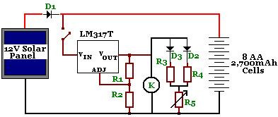
When the panel isn't generating, the entire circuit is off and there is absolutely no current drain from the battery. When the sun gets up and panel starts producing at least 10 Volt, the LED lights and the two...
The circuit is designed to power a CCTV camera, provide lighting inside a nestbox, and charge batteries using a photovoltaic (PV) solar panel. It includes a circuit diagram for a solar-powered wireless CCTV camera with battery backup. D1 is...
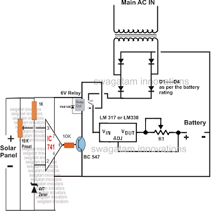
The automatic changeover relay circuit was requested by Mr. Karimulla Baig. The circuit is designed to charge a connected battery at a constant current using power from a solar panel. In the absence of solar energy, such as during...
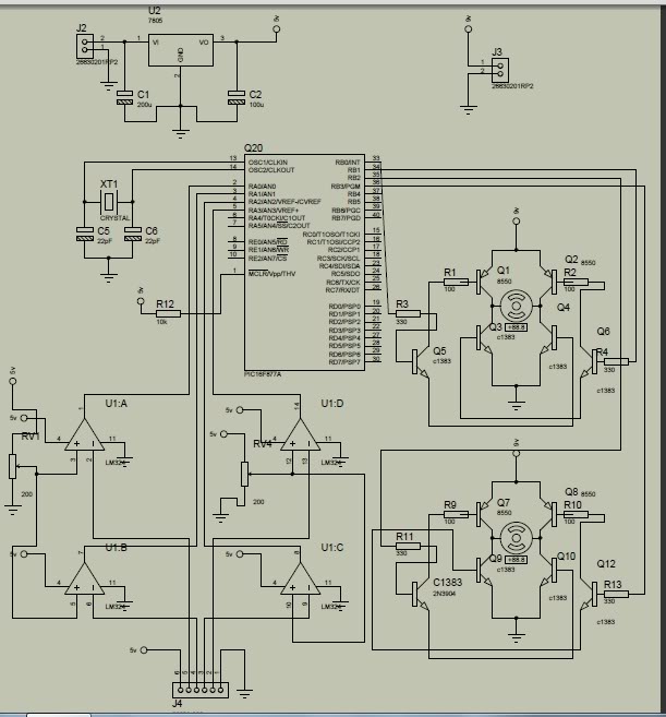
This is a microcontroller hobby project featuring a line-following mobile robot named "Cruddy." The name reflects the somewhat messy structure of the robot. As a first-time builder, the soldering skills may not be fully developed. The chassis was sourced...
The basic circuit using the L293 forms an H-Bridge driver, as shown in Figure 1, is designed for controlling inductive loads like DC motors. External diodes are necessary for suppressing back EMF. The MiniBoard utilizes the L293D, which features...
The device utilizes body heat to identify and track its human operator. Central to its heat-seeking function is the Devantech TPA81 Thermal Sensor Array, which features an array of eight horizontally mounted detectors. Each detector is capable of sensing...