
Sound-modulated light source

The described circuit utilizes a transistor configured as a peak detector to modulate light intensity based on audio input. The 10 K potentiometer allows for fine-tuning the voltage bias at the base of the transistor, ensuring that it operates within the desired threshold for detecting peaks in the audio signal. When the audio signal exceeds this threshold, the transistor conducts, enabling current to flow through the gate of the SCR.
The SCR acts as a switch that controls the power delivered to the bulb. As the audio signal fluctuates, the SCR turns on and off, leading to variations in the bulb's brightness corresponding to the amplitude of the sound. This modulation creates a visual representation of the audio signal, providing an engaging effect.
In applications where a quicker response is required, the capacitor C2 can be removed. This alteration reduces the circuit's time constant, allowing the SCR to react more swiftly to changes in the audio signal. However, it is essential to consider that eliminating C2 may lead to a less stable operation under certain conditions, potentially resulting in flickering of the bulb.
Overall, this circuit exemplifies a simple yet effective method for visualizing audio signals through light modulation, combining basic electronic components to achieve a dynamic interaction between sound and light.This circuit modulates a light beam with voice or music from the output of an amplifier. If the 10 K pot is adjusted to slightly less than the Vbe of the transistor, the circuit forms a peak detector This drives the gate of the SCR, lighting the bulb whose brightness will vary as the sound level varies. C2 may be removed for a faster response.
Related Circuits
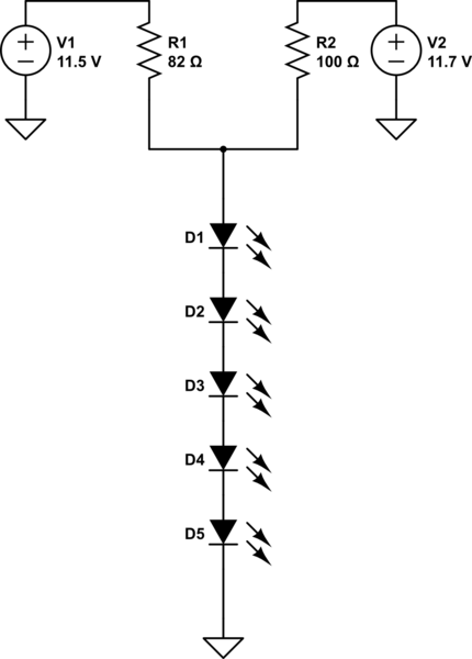
A series of LEDs is intended to display at two brightness levels, and there is uncertainty regarding the proper wiring. This setup is for additional running lights and brake lights on a bicycle. When using the series LED calculator,...
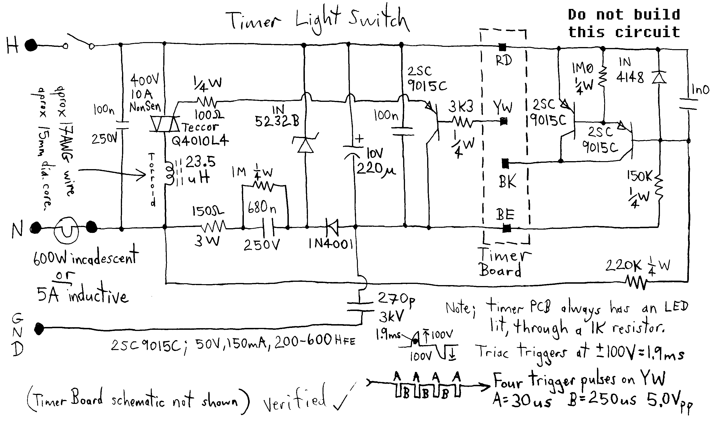
Typical circuit representative of those used in most light switch type digital timers. The timer module is normally a PIC or custom chip, and it syncs to the AC line so that a trigger pulse can be supplied at...
White LEDs have a rated current at a voltage drop of about 3.3 to 3.4 V. It is ideal to be powered from the battery voltage which is slightly larger. Then there is the best energy used. In this...
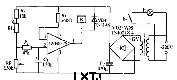
Automatic lights using a light sensor, the TWH87SL power switch integrated circuit consists of a first input terminal TWH8751 connected to the positive terminal of the power supply. The output pin state is determined by the strobe terminal, which...

The Multiport W723 is an adjustable constant current regulator designed for use in switching regulator circuits, capable of delivering an output current of 1A. In the illustrated circuit, the W723 reference base voltage is approximately 7.2V. This voltage is...
This circuit utilizes a 555 timer configured to operate in astable mode. This configuration produces a continuous output at Pin 3 in the form of a square wave. When the timer's output transitions to a high state, it triggers...