
Switching the constant current source consisting of the application circuit W723

The Multiport W723 adjustable constant current regulator is a sophisticated circuit designed for efficient power management in various applications. The circuit operates by utilizing a feedback mechanism that maintains the output current at a constant level, regardless of variations in load. The reference voltage of approximately 7.2V serves as a critical threshold for regulating the output current.
The voltage division performed by resistors R1 and R2 ensures that the non-inverting input receives a stable reference voltage, which is essential for the accurate functioning of the regulator. The inverting input receives a voltage derived from resistors R3 and R4, which allows for fine-tuning of the output current through the feedback loop. The configuration of R4 in conjunction with shunt resistor R5 is crucial for establishing the desired current threshold, with the voltage drop across R5 providing a direct measurement of the output current.
The role of resistor R6 in adjusting the output ripple current is significant, as it allows for the optimization of performance under varying load conditions. The feedback mechanism ensures that any increase in load results in a corresponding increase in the regulator's output, thus maintaining the desired current level.
The activation of the output stage, triggered by the current feedback, results in a pulse of 12mA at the Uin terminal, which is essential for driving the transistor VT. The inclusion of the Zener diode VD1 is a critical design choice, as it stabilizes the output stage biasing, ensuring reliable operation under different conditions. The diode VD2 serves as a protective measure against reverse voltage spikes, which can occur during switching events.
The filtering stage, composed of capacitor C1 and inductor L, is essential for smoothing the output waveform, minimizing voltage ripple, and ensuring a stable output current. The operating frequency of the circuit, typically around 20kHz, is influenced by the load, highlighting the adaptability of the W723 regulator in various applications. Overall, this circuit exemplifies the principles of efficient power regulation and stability in electronic design. As shown in FIG Multiport W723 is being integrated adjustable constant current regulator composition application switching regulator circuit, the output current of 1A. Illustra ted circuit, W723 reference base voltage (approximately 7.2V) through R1, R2 dividing the voltage of approximately 3V added to the non-inverting input, and also via a resistor R3, R4 partial pressure after adding to the inverting input, R4 and another low-end shunt resistor R5 connected. When the inverting and non-inverting input of approximately balanced, the shunt voltage drop across the resistor R5 is about 1V.
R6 is used to adjust the output ripple current. When the current feedback circuit increases, the regulator output stage unit is turned on, W723 Uin end a current pulse of 12mA, the driving transistor VT. Zener diode VD1 regulator unit used to bias the output stage, and the diode VD2 is used to eliminate the reverse spikes.
Capacitor C1 and inductor L filter composed to smoothly switch the output waveform. The size of the maximum operating frequency depends on the load, typically 20kHz.
Related Circuits
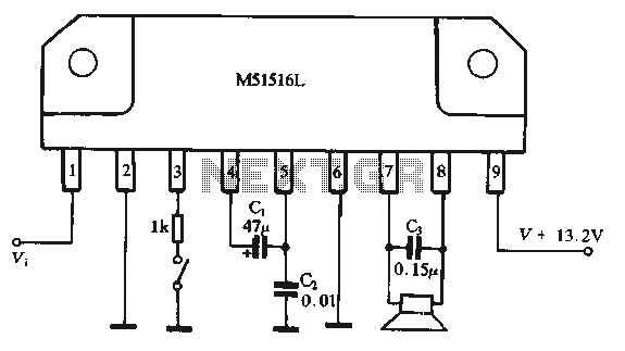
Figure 1-44 illustrates a dedicated BTL (Bridge-Tied Load) amplifier circuit, which consists of two single amplifiers. The relevant components are integrated into the circuit, simplifying the connections. The circuit operates at a power supply voltage of 13.2V and can...
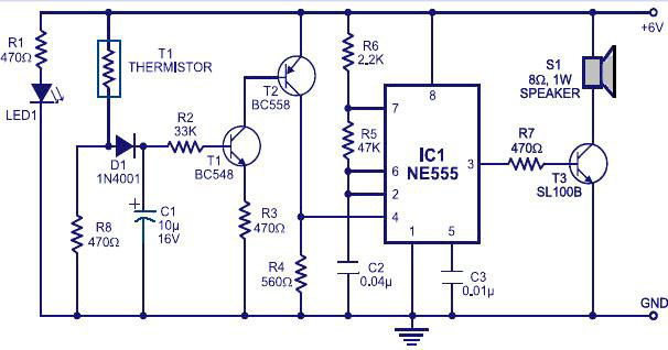
Various fire alarm circuits are discussed, featuring a new design that utilizes a thermistor and a timer. This circuit is straightforward and can be easily implemented. The thermistor exhibits low resistance at high temperatures and high resistance at low...
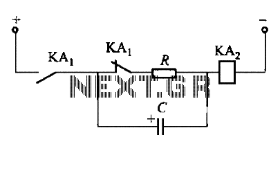
To fulfill the requirements of a control loop, it is often necessary to utilize an electromagnetic relay or a transistor relay to either accelerate or delay an action, thereby forming an acceleration or delay circuit. The circuit depicted in...
Switch-mode power supplies are utilized in electronic circuits to efficiently increase (step up) or decrease (step down) voltage levels. In comparison to linear voltage regulators, switch-mode supplies convert minimal energy into heat, resulting in high efficiency. This characteristic is...
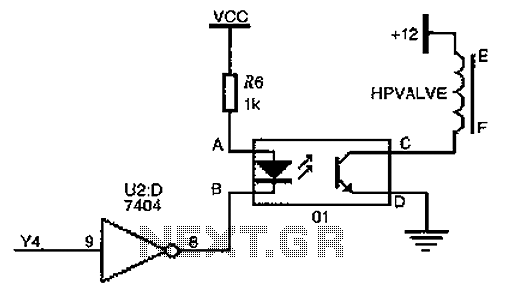
The driver circuit for the high-pressure natural gas shut-off valve utilizes solid-state relays. In dual-fuel mode operation, the fuel switching mechanism is controlled by a logic section that activates Y4 to a high state via U2 (7404 inverters). This...
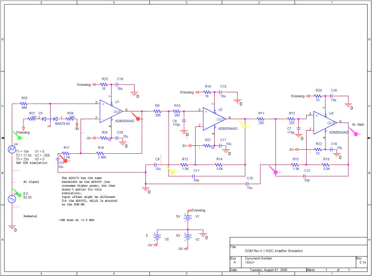
A bandwidth-limited amplifier shapes the waveform sampled by the 40 MHz high-speed pipeline Analog to Digital Converter (fast ADC, or fADC). It is well known that the shaping time is twice the time constant (peaking time) for each pole...