
sound via laser light

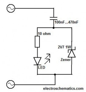
The described circuit modification enhances the functionality of a basic sound transmission system by utilizing a laser diode instead of a standard LED. The implementation involves careful selection of components to ensure compatibility and performance. The red laser diode, chosen for its visibility and efficiency, operates optimally at a voltage of 4.5V, which is safely within the recommended limits to prevent damage. The current draw of approximately 30 mA is manageable for the BC548 transistor, which acts as a switch to control the laser's operation based on audio input signals.
The method for removing the laser casing is a critical step, as it allows for better integration of the laser diode into the overall circuit. The use of a black plastic pen casing serves both aesthetic and functional purposes, providing a lightweight and sturdy housing for the laser component. The wooden blocks provide stability and allow for easy adjustment of the laser beam's position during setup.
Additionally, the incorporation of an oscilloscope to visualize the output signals when a remote control is used adds an educational aspect to the project. It enables students to observe the modulation patterns generated by different button presses, reinforcing the concepts of digital signal transmission and modulation. This practical application of electronics not only enhances learning but also demonstrates the versatility of laser technology in communication systems. Overall, this circuit design exemplifies an effective approach to improving sound transmission distance while maintaining user engagement and educational value.The transmission distance can be increased greatly by replacing the transmitter`s red LED with a cheap red laser diode purchased from a $2 Dollar Shop . The circuit design makes a compromise between laser brightness and sound quality and loudness. This is because the laser needs to be bright enough so that it is easy to locate the beam when posi tioning the receiver and for students to see that the laser beam is really there and carrying` the sound. Do not apply any more than 5 volts to the laser diode. I find that 4. 5 volts from 3 AA cells works well. At that voltage the laser draws about 30 mA allowing a cheap general purpose NPN bipolar transistor (such as the BC548) to work well in modulating the current through the laser.
The laser casing needs to be removed. I cut carefully along the metal casing using a fine hacksaw and then prise it off the laser barrel with long-nosed pliers. The photo alongside shows the laser barrel inserted in a black plastic pen casing which is itself mounted in a small wooden block glued to the larger block.
This is particularly useful when a remote control is shone` at the receiver. Then the oscilloscope can display the different digital patterns when each of the remote control keys are pressed. 🔗 External reference
Related Circuits
This circuit should only be attempted by individuals with a strong understanding of electronic devices. It is connected to a main power source (220V) and poses a risk of high electrical shock. This circuit operates at a mains voltage of...

This project involves a high-fidelity external USB sound card or USB headphone system designed for use with PCs or Macs. It utilizes the PCM2706 integrated circuit, which serves as a high-quality, crystal-clear 16-bit stereo digital-to-analog converter (DAC). The PCM2706...
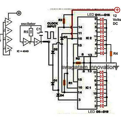
Decorative lights arranged in various moving patterns are visually appealing and have gained significant popularity in today's world. While more complex lighting arrangements may require the use of microcontroller ICs, simpler yet captivating light effects can be generated using...

This circuit can control the on/off cycle of a light using a CDS photocell and turn it off after a preset period. The light can only be activated when the CDS cell is in darkness, and it remains on...

This circuit generates a two-tone effect similar to the cuckoo song. It can be utilized for doorbells or other applications due to its integrated audio amplifier and loudspeaker. As a sound effect generator, it can connect to external amplifiers,...
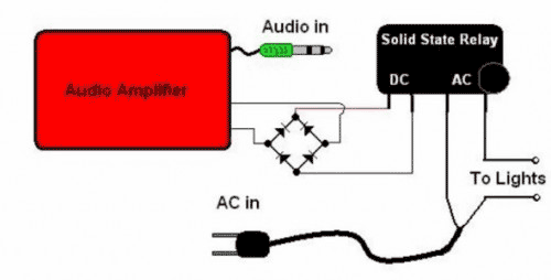
The basic Idea was to have Christmas lights flash with the music. In my design I use an ordinary amplified computer speaker, a diode bridge, and a ‘CRYDOM’ SSR (Solid State Relay). In order to increase the time that...