
Space Horticulture Circuit

The proposed circuit operates effectively within the specified parameters, utilizing a 555 timer IC configured in astable mode to generate a square wave signal at 3Hz frequency with a 50% duty cycle. The duty cycle indicates that the LED will be on for half of each cycle, ensuring a balanced illumination effect during operation. The choice of a 1µF capacitor is critical in determining the timing intervals, as it directly influences the charge and discharge rates within the 555 timer circuit.
The TIP120 transistors serve as the primary switching elements in this design. The first TIP120 (T1) is responsible for modulating the power delivered to the strobe LED lighting module, effectively turning it on and off in response to the output from the 555 timer. The second TIP120 (T2) acts as a compensatory element, addressing the voltage drop experienced by T1. By maintaining the voltage drop across T1, T2 ensures that the control LED modules receive a consistent voltage level, thereby achieving uniform brightness across all LEDs.
In this configuration, resistor R4 plays a vital role by providing a forward bias to T2, keeping it continuously in the 'on' state when power is supplied. This arrangement ensures that the control LED modules operate effectively without experiencing fluctuations in brightness caused by variations in the voltage drop across T1.
The power supply for the entire circuit is a 12 VDC wall transformer, which is a common and practical solution for such applications. The integration of an AC appliance timer allows for automation of the lighting system, enabling it to operate for a predetermined duration (12 hours in this case), which is particularly useful for applications requiring periodic illumination.
Overall, the design effectively combines timing, switching, and power management to achieve the desired strobe effect while ensuring consistent performance across the LED modules. The schematic representation of the circuit, including the arrangement of components and connections, is essential for visualizing the operational flow and verifying the integrity of the design.The optimum duty cycle and frequency for the strobe photoperiod needs to be determined. In other words we`re flying blind in regard to optimum frequency and duty cycle. The circuit I designed is 3Hz with a 50% duty cycle. I chose this frequency based upon using a convenient 1-uF capacitor, for a 555 timer IC. The schematic is shown in figure 2 (be low). The output from the 555 timer (pin 3) is connected to the base of NPN Darlington Transistor (TIP120) T1. The NPN transistor switches the current on and off to the strobe LED lighting module. There is a voltage drop across the collector-emmiter of the TIP 120 transistor. To insure the equal brightness from both the LED modules, I place a dummy TIP120 transistor, T2, in line with the control LED module (see figure 3, below).
The transistor T2 matches the voltage drop across T1 to help supply an equal voltage to the control LED modules. The T2 transistor is kept forward bias (always on), when power is applied through resistor R4 (2. 2K ohm). The voltage drop I measured across the TIP120 transistors is approximately 1. 5 volts. An overall view is shown in figure 4 (above). A 12 VDC wall transformer powers the circuit. The wall transformer is plugged into an inexpensive Radio-Shack AC appliance timer set for a 12 hour on period.
The wall transformer supplies voltage to both circuits. 🔗 External reference
Related Circuits
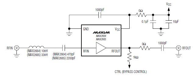
A simple, low-cost, and ultra-compact VHF/UHF low-noise amplifier circuit can be designed using the MAX2664 and MAX2665 ultra-compact LNAs for VHF/UHF applications. These devices incorporate a broadband LNA with an integrated bypass switch. The MAX2664 covers the UHF frequency...
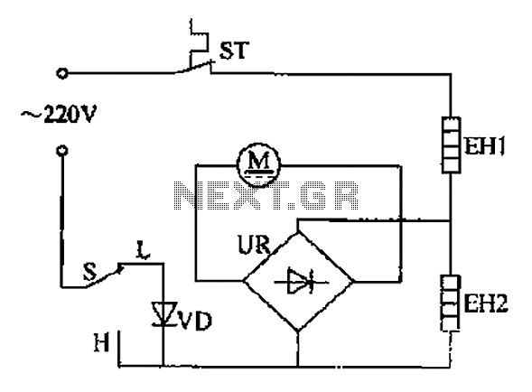
The comb electric circuit illustrated in Figure 1-3 features two temperature settings. By toggling switch S to either the L or H position, different temperatures can be achieved. Once switch S is activated, the circuit powers the heating wires...
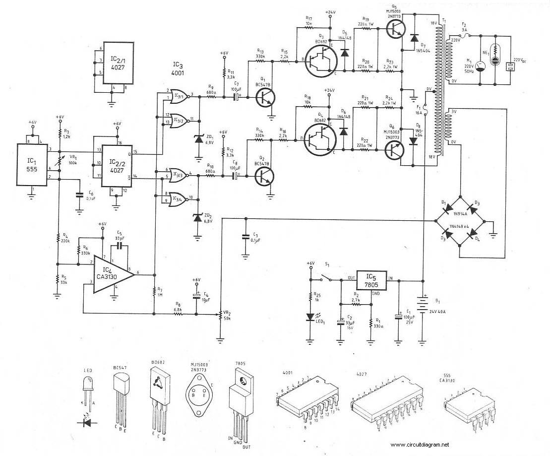
This is the schematic diagram of a 300W power inverter circuit. The inverter utilizes the MJ15003 power transistor for final amplification. If the MJ15003 transistor is difficult to source, it can be replaced with a 2N3773. The inverter is...
If the transmitter stick-potentiometer delivers a voltage about 2 - 3 V, this circuit will be suitable. If you want to avoid using the battery cable (supplying Vcc for IC1 and -2), you can use a separate 5V supply...

The continuity tester consists of a battery and a lamp connected in series, with one end of the circuit terminated with an alligator clip and the other end connected to the probe tip. The continuity tester is a fundamental...
WB5LUA described GaAsFET preamplifiers for several microwave bands, which included an active bias circuit for the GaAsFET. Although newer devices have been introduced that offer improved performance, they require different bias points with varying currents and voltages. Modifying the...