
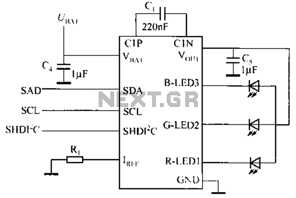
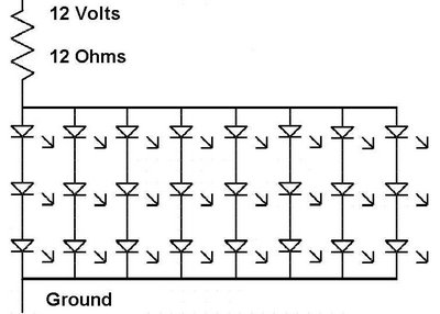
LED strobe has independent delay and duration

The circuit described serves a critical role in the quality control of fuel injectors by facilitating the visual inspection of the spray pattern. The design is characterized by its simplicity, which makes it both cost-effective and easy to implement.
The circuit typically incorporates a low-power LED light source that is modulated to provide adequate illumination for the inspection process without overwhelming the observer. The choice of LED technology is significant, as LEDs offer a compact form factor and lower heat generation compared to traditional strobe lights. This allows the circuit to be integrated into tighter spaces where conventional lighting solutions would be impractical.
To achieve the desired visual effect, the circuit may include a microcontroller that regulates the LED's brightness and pulse width. This modulation can be adjusted to match the specific requirements of the inspection environment, ensuring that the fuel injector spray pattern is clearly visible without causing glare or reflections that could impede analysis.
Additionally, the circuit could employ a lens or optical filter to enhance the visibility of the spray pattern. This optical component would be designed to focus the emitted light onto the fuel injector, optimizing the viewing angle and intensity for the inspector.
In summary, the circuit is an effective solution for inspecting fuel injectors, providing a reliable and manageable alternative to xenon strobe lights. Its design focuses on compactness and control, ensuring that it meets the necessary requirements for quality assurance in fuel injection systems.This circuitis not complex, but it saved the day in an application involving visual inspection of the spray pattern of fuel injectors for quality and consistency. In this application, xenon strobe lights did not work because they take up too much space, and the light they emit is too intense.
🔗 External reference
Related Circuits

An embedded C-based RF-controlled robot equipped with a metal detector, along with wireless image and voice transmission capabilities. This project report is intended for electronics and communication engineering students. The project involves the design and implementation of an RF-controlled robot...
The circuit-delay relay for speakers serves as a delay mechanism that prevents the immediate activation of speakers when the amplifier is powered on. This feature is designed to protect the speakers from potential damage caused by sudden power surges....
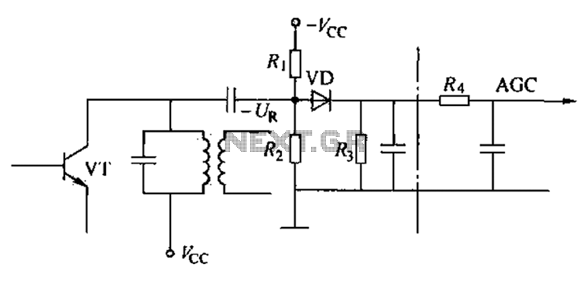
Commonly referred to as an automatic gain control (AGC) circuit, it is primarily utilized in receivers. This circuit maintains a constant output voltage amplitude despite variations in the input signal amplitude. It ensures that the receiver can effectively process...
Watching the time on a mobile phone in the dark can cause discomfort due to the strong contrast between bright and dark backlighting. To address this issue, the "ICON" model is utilized, which operates in standby mode with a...
The schematic below illustrates a simple LED flasher circuit. This circuit utilizes three LEDs that begin to blink or flash upon receiving a 9-volt supply. It is straightforward in design, employing a self-flashing LED (LED 1) to trigger the...
The issue with this monitor is that the power supply for the vacuum tube backlighting fails. The initial step involves completely disassembling the monitor into smaller components, followed by the careful removal of the gold-colored trays that hold the...