
spi schematics

The schematic for the SPI Supplies Faraday Cup is designed to facilitate accurate measurements of electron beam currents, a critical parameter in electron microprobe applications. The Faraday Cup operates by capturing electrons emitted from a beam, allowing for precise current measurements that are essential for calibrating the system's performance.
The design includes several key components: a conductive cup that collects the electrons, a current amplifier to enhance the signal for measurement, and a digital interface for data logging and processing. The Faraday Cup is connected to a power supply that ensures proper operation of the current amplifier, and the output is routed to a microcontroller, which may be an Atmel AVR or a device from the 8051 series. This microcontroller processes the captured data and interfaces with other system components, allowing for real-time monitoring and adjustments based on the measured current.
The schematic should also include details on the power supply requirements, typical voltage levels, and the connections for the input and output signals. Proper grounding and shielding techniques are essential to minimize noise and ensure accurate measurements. Additionally, provisions for calibration and maintenance should be indicated to support the longevity and reliability of the device in various operational environments.
Overall, the schematic provides a comprehensive guide for assembling and utilizing the SPI Supplies Faraday Cup, ensuring that users can achieve high precision in their electron microprobe measurements.Schematic for the SPI Supplies Faraday Cup Take a detailed look at the diagrams for the SPI Supplies stand-alone Faraday Cup for calibrating beam currents in wavelength dispersive electron microprobes and . -> Atmel AVR and 8051 series ISP.. 🔗 External reference
Related Circuits
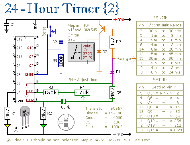
These two circuits are multi-range timers that offer periods of up to 24 hours and beyond. They can function as repeating timers or single-shot timers. Both circuits are fundamentally the same, with the primary distinction being their behavior in...
The controller for a Hybrid Power Plant (HPP) block diagram consists of 440 Wp photovoltaic modules, a 1 kW wind turbine, and a 5 kW diesel engine as a backup. The HPP functions as a centralized PV and wind...
Here are some schematics and information that can be difficult to locate elsewhere. If there are schematics that should be included in this collection, please feel free to reach out. The intention is to expand this collection over time,...
This chapter contains circuit diagrams for various power supplies designed for pulsed solid-state lasers. These include units suitable for driving the widely used Hughes ruby and YAG rangefinder laser assemblies, as well as one utilizing the flash from a...
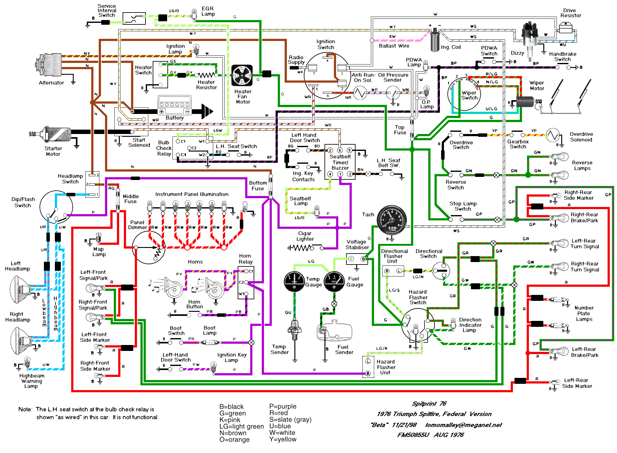
The Haynes manual is quite confusing regarding the labeling of relays on Spitfires. The two main sources of confusion are: 1. The illustrations depict right-hand drive cars with different relay locations, and 2. The naming of the relays is...
This simple circuit combines two or more audio channels into a single channel (for example, mixing stereo into mono). The circuit is capable of mixing an arbitrary number of channels while consuming minimal power. Although the schematic illustrates two...