
Spring Reverb Unit

The one I have is an Accutronics (they are still going, so check out their web site - see below), but you might already have one, or can get something different, so you will have to experiment. The basic spring reverb chamber is a simple affair, with an input and output transducer, and one or more (usually three or four) springs lightly stretched between them. Each spring should have different characteristics, to ensure that the unit produces a rich and varied reverb sound.
A typical spring reverb circuit consists of an input signal path that feeds into a transducer, typically a piezoelectric element, which converts the electrical signal into mechanical vibrations. These vibrations are then transmitted through the springs, which act as resonators. The output transducer, also usually a piezo element, picks up the vibrations from the springs and converts them back into an electrical signal for further processing or amplification.
The design may include additional components such as op-amps for signal amplification, filters to shape the frequency response, and possibly a feedback loop to enhance the reverb effect. The choice of springs, their length, and tension will significantly influence the tonal characteristics of the reverb produced.
In practical terms, the layout of the circuit board should minimize noise and interference, with careful consideration given to the placement of components to reduce the potential for unwanted vibrations affecting the signal path. Proper grounding techniques should also be employed to ensure a clean output.
Overall, while the basic design of a spring reverb unit is straightforward, the nuances of component selection and configuration can lead to a wide variety of sonic results, making experimentation a key aspect of developing a unique spring reverb sound.Spring reverb units are most commonly used in guitar amps, having been replaced by digital effects in most other areas. This cannot really be classed as a "real" project, because the circuitry is somewhat experimental, and may change quite dramatically depending on the type of spring reverb unit you can actually get your hands on.
The one I have is an Accutronics (they are still going, so check out their web site - see below), but you might already have one, or can get something different, so you will have to experiment. The basic spring reverb chamber is a simple affair (see Figure 1), with an input and output transducer, and one or more (usually three or four) springs lightly stretched between them. Each spring should have different characteristics, to ensure that the u 🔗 External reference
Related Circuits
The circuit is designed for conducting safe experiments with high-voltage pulses and operates similarly to an electrified fence generator. The pulse repetition frequency (PRF) is dictated by the time constant of the R1-C3 network within the feedback loop of...
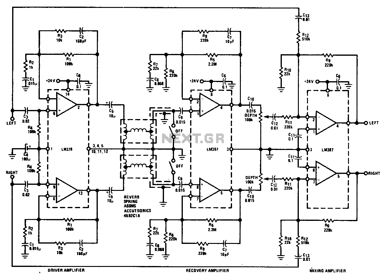
The LM378 dual power amplifier serves as the spring driver. The recovery amplifier is a low-noise dual preamplifier. Mixing of the delayed signal with the original is accomplished using another LM387 configured in an inverting summing arrangement. The LM378 is...
A listener positioned at a distance from a sound source perceives sound as a combination of direct sound and indirect sound that has been reflected off the boundaries of the listening area. These reflections are known as reverberation. Reverb...
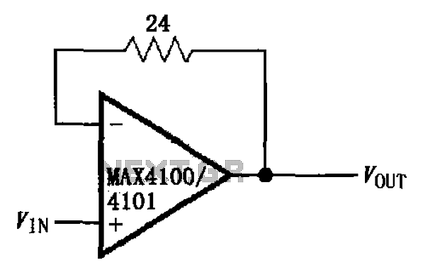
The circuit illustrated is a unit gain buffer circuit utilizing the MAX4100/4101 operational amplifiers. It incorporates a small resistor (24 ohms) within the feedback loop of the amplifier, thereby establishing a unity gain buffer. This configuration maximizes the bandwidth...
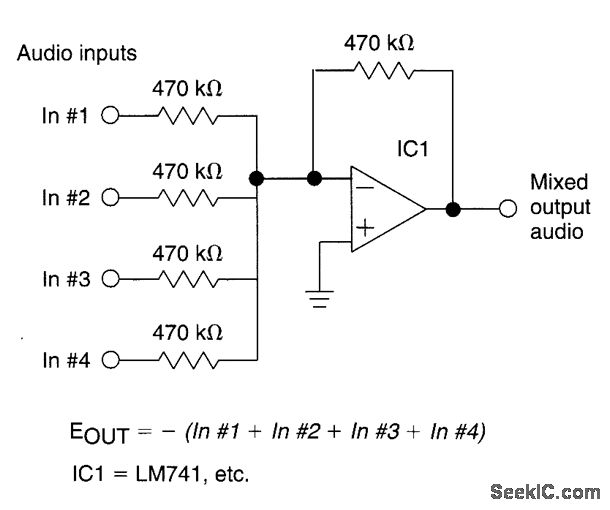
The circuit features four inputs. The voltage gain between each input and the output is maintained at unity by the relative values of the 470kΩ input resistor and the 470kΩ feedback resistor. The described circuit operates as a voltage buffer...
Professor Steven E. Jones' circuit demonstrates an 8x overunity. The concept of overunity refers to a system that produces more energy than is consumed, effectively achieving a coefficient of performance greater than one. In the context of Professor Steven E....