
stabilizer circuit

The described circuit is designed to provide a reliable and adjustable power supply for various electronic applications. It features a voltage regulator that ensures a stable output voltage, which can be set anywhere between 0 and 30 VDC, catering to a wide range of experimental needs. The adjustable nature of the output voltage is achieved through a potentiometer that allows users to fine-tune the voltage level according to specific requirements.
The electronic current limiter is a critical component of this circuit. It is implemented using a combination of operational amplifiers and transistors, which monitor the output current and compare it to a set threshold. When the output current exceeds the predetermined limit, the circuit automatically reduces the output voltage to prevent damage to the connected load. This feature is particularly useful in laboratory settings where sensitive components may be tested, as it protects against accidental overloads.
Moreover, the visual indication of the current limiter's operation is typically achieved using an LED that illuminates when the current limiter is active. This allows users to quickly assess the status of the power supply at a glance, ensuring that experiments can be conducted with confidence, knowing that the equipment is protected.
Overall, this power supply circuit is an invaluable tool for electronics experimentation, providing both versatility in voltage output and safety through its current limiting capabilities. Its design emphasizes user-friendliness and reliability, making it suitable for both amateur and professional applications in electronics testing and development.This is a circuit for high quality power supply with a continuously variable stabilized output adjustable at any value between 0 and 30VDC. The circuit also incorporates an electronic output current limiter that effectively controls the output current from a few milliamperes (2 mA) to the maximum output of three amperes that the circuit can delive
r. This is the figure of the circuit; This feature makes this power supply indispensable in the experimenters laboratory as it is possible to limit the current to the typical maximum that a circuit under test may require, and power it up then, without any fear that it may be damaged if something goes wrong. There is also a visual indication that the current limiter is in operation so that you can see at a glance that your circuit is exceeding or not its preset limits.
🔗 External reference
Related Circuits

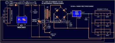
The circuit operates by activating switch SA1, which powers a 220V transformer that converts AC voltage to DC through a bridge rectifier, supplying power to the computer control panel. The temperature for cooking food is set on this control...
Most peripherals that interface with a PC utilize a USB port. The computer's power supply circuit, specifically the switched-mode power supply (SMPS), is designed to provide constant power to all internal components. However, when external peripherals that require a...
The circuit utilizes relay control. The voice switch operates as follows: upon the first clap, the load (lights) is activated; upon the second clap, the load (lights) is deactivated. This system can be employed to control lighting in residential...
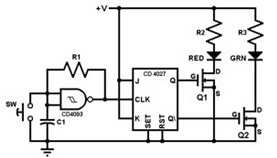
This project involves constructing a coin toss circuit that comprises three main sections: a square-wave oscillator, a JK flip-flop, and two LEDs (one red and one green). The circuit utilizes CMOS digital integrated circuits (ICs) and MOSFET transistors. The...
Using an old moving coil instrument, it is easy to create a simple voltmeter that indicates the status of a telephone line at a glance. The circuit's high input impedance allows it to be permanently connected to the line,...
This 555 timer circuit toggles a relay when a button is pressed. Pins 2 and 6, which are the threshold and trigger inputs, are maintained at half the supply voltage by two 10K resistors. When the output is high,...