
Stepless triac dimmers

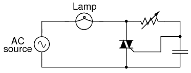
The circuit described utilizes a closed switch S to control the flow of 220V AC power through a series of components, including resistors RP1 and RP2, and a capacitor C2. The primary function of this configuration is to manage the dimming of lighting by regulating the amount of voltage applied to lamp H. The diac VD serves as a voltage-sensitive switch that activates when the voltage across C2 exceeds its breakover threshold. Upon activation, the diac triggers the triac, which subsequently allows current to flow through the lamp H, causing it to illuminate.
The operation of this circuit hinges on the behavior of the capacitor C2, which charges during the positive half-cycle of the AC waveform. Once the voltage across C2 reaches the breakover voltage of the diac, the diac conducts, allowing current to flow through the triac and energizing the lamp. When the AC waveform crosses zero and transitions to the negative half-cycle, the diac and triac turn off, interrupting the current flow. This process repeats with each AC cycle, creating a pulsed output to the lamp.
The symmetrical nature of the AC waveform means that the conduction times during the positive and negative half-cycles are equal under normal conditions. However, by varying the resistance of the regulator RPI, the charge time of capacitor C2 can be manipulated. A higher resistance increases the charge time, delaying the trigger point of the diac, while a lower resistance decreases the charge time, allowing for an earlier trigger. This adjustment effectively alters the conduction angle of the triac, which in turn changes the average voltage applied to lamp H. As a result, the brightness of the lamp can be smoothly adjusted, achieving the desired dimming effect without abrupt changes in illumination.
This dimming control circuit is widely applicable in various lighting systems, providing flexibility in managing light levels to suit different environments and preferences. Proper selection of components, such as the values of resistors RP1, RP2, and the capacitance of C2, is crucial for achieving optimal performance and ensuring safe operation within the specified voltage ratings. Closed lights switch S, 220V AC via RP1, RP2 R and the capacitor C2 is charged when the voltage across C2 reaches diac breakover voltage of VD, VD and triac vs sequentially tur ned on, the controlled lighting H lamp is energized to emit light. When the AC zero-crossing is reversed, vs off on their own, C2 began to reverse charge, repeat the process. Seen within each AC cycle, vs positive and negative half-cycle are symmetrical conduction time. If the size of the resistance regulator RPI, it will change the charge rate of the capacitor C2, thereby making any half weeks vs trigger on-time forward or backward, that is changing vs conduction angle size, the corresponding increase in both ends of the lamp H the average voltage also changes, it can achieve the purpose of stepless dimming.
Related Circuits

The circuit consists of two separate 3023 optoisolators controlling two distinct triacs, each responsible for powering a large 3-phase contactor. One contactor operates correctly, while the other experiences issues, not receiving sufficient power to engage fully. The upper image...

This design is likely to generate significant radio frequency interference (RFI) without the incorporation of a choke. The house wiring serves to limit the rate of change of current (di/dt). It is a cost-effective design that demonstrates hysteresis at...
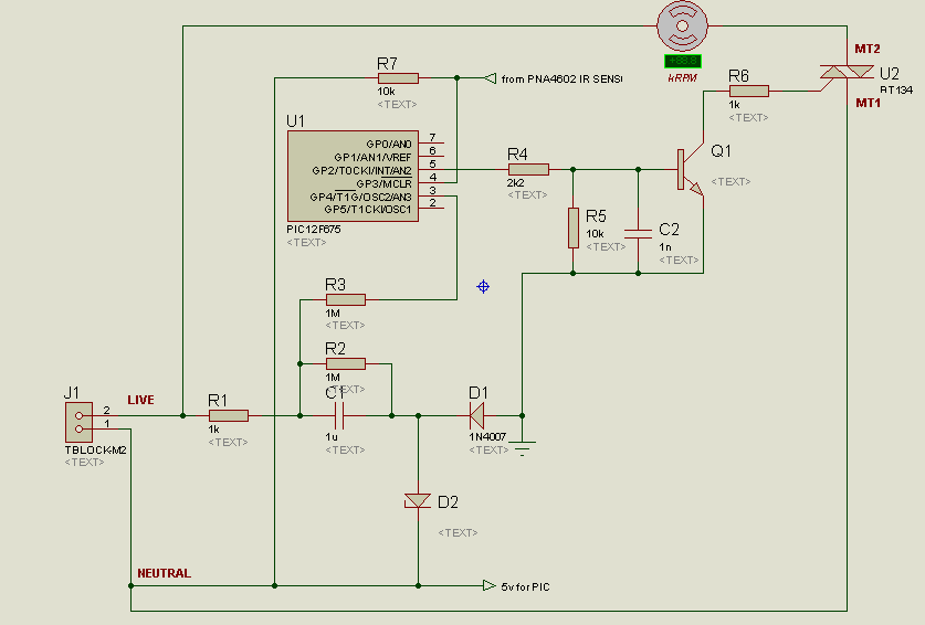
A project is underway to control the speed of an electric fan (220Vac, 60W, 5A max.) automatically using a microcontroller based on certain parameters. The circuit design for controlling the speed of an electric fan involves several key components to...
SCRs are unidirectional current devices, making them suitable for controlling direct current (DC) only. When two SCRs are connected in a back-to-back parallel configuration, they can be utilized for specific applications. SCRs, or Silicon Controlled Rectifiers, are semiconductor devices that...
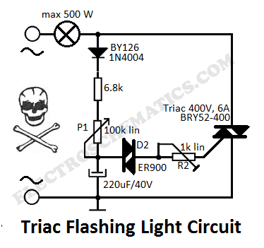
This flashing light circuit utilizes triacs to produce an intermittent light with variable frequency. Additional components include the D1 diode and a semi-adjustable resistor. The flashing light circuit is designed to create a visual indication through intermittent illumination, which can...
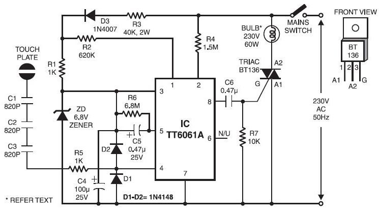
Typically, when a car door is closed, the dome light turns off immediately. This circuit allows the dome light to gradually fade in brightness before eventually turning off. An electronic transformer dims halogen lamps and is a straightforward device...