
Intelligent Battery-Charging Circuit Circuit

The described charging circuit is specifically designed for Nickel Cadmium (NiCad) batteries, but its versatility allows it to accommodate various battery types. This circuit includes a low-battery detection feature, which is crucial for preventing over-discharge and extending battery life. The detection mechanism is adjustable, allowing for customization of the trip voltage through a 500 kΩ potentiometer. This means that the user can set the voltage level at which the circuit will trigger the low-battery alert, ensuring that the batteries are not depleted beyond their safe operating limits.
The selection of the resistor (Rc) is an important aspect of the design, as it directly affects the charging characteristics of the circuit. The appropriate resistor value should be chosen based on the specific battery chemistry and capacity being used. This selection process ensures that the charging current is optimized for the selected battery, enabling efficient and safe charging.
The schematic for this circuit should include the power supply input, the charging path with the selected resistor, the potentiometer for setting the trip voltage, and the low-battery detection circuitry. The low-battery detector typically consists of a comparator or a similar device that monitors the voltage across the battery. When the voltage drops below the predetermined threshold set by the potentiometer, the circuit can activate an alarm or indicator, alerting the user to the low battery condition.
In summary, this charging circuit is a robust solution for NiCad batteries, featuring adjustable trip voltage and customizable charging parameters, ensuring optimal performance and longevity of the battery pack. Proper implementation and component selection are critical for achieving the desired functionality and reliability of the circuit. Intended for a Nicad application this charging circuit can be used with a wide range of batteries. A low-battery detector is intended. The trip voltage is set via the 500-kQ pot. Select Rc for the battery you intend to use.
Related Circuits
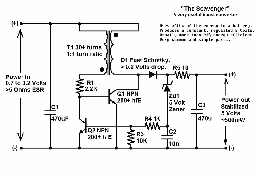
Presented here is a significant advancement in the design of simple, cost-effective, and efficient boost converters. To achieve an effective design, it is essential to convert current to voltage as efficiently as possible. This circuit excels in this regard. The...
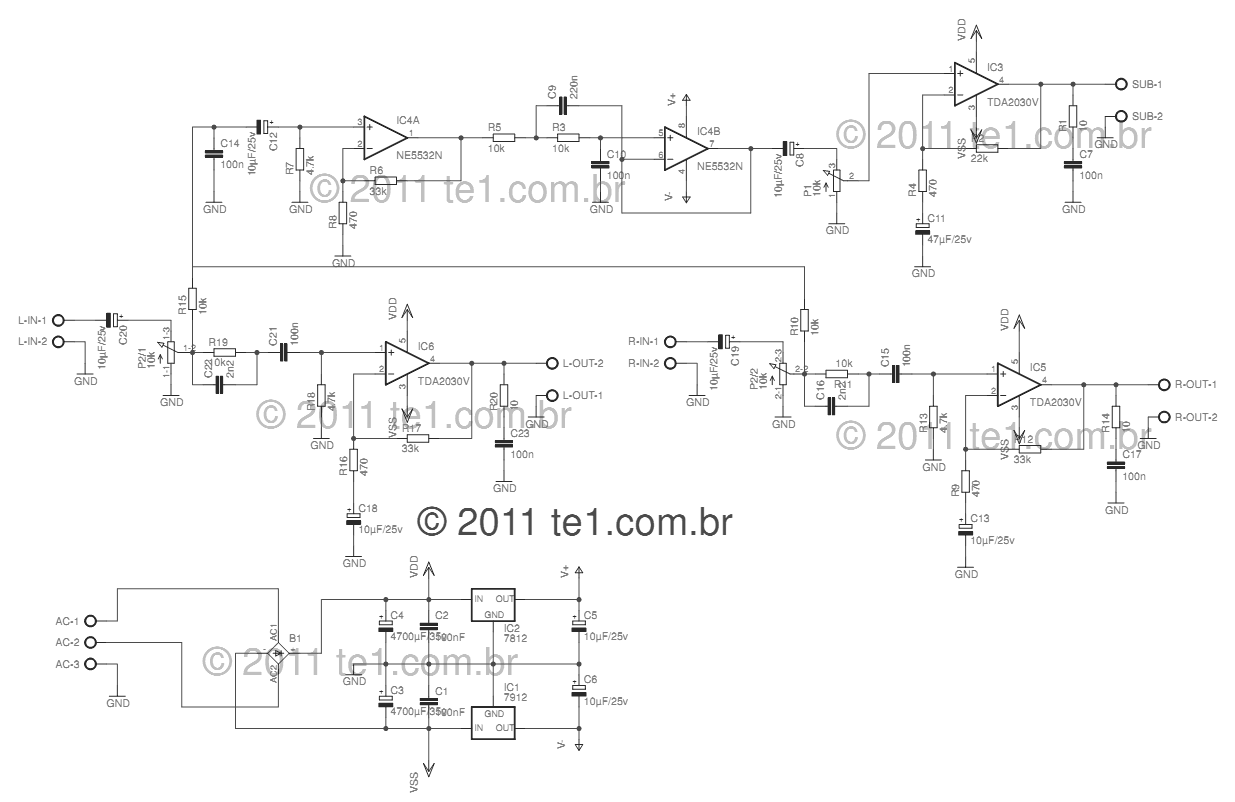
This circuit is a complete application for a 2.1 amplifier system, consisting of two satellite speakers powered by a TDA2030 and one subwoofer. This 2.1 system is commonly utilized in commercial applications as an amplifier for computers, enhancing audio...
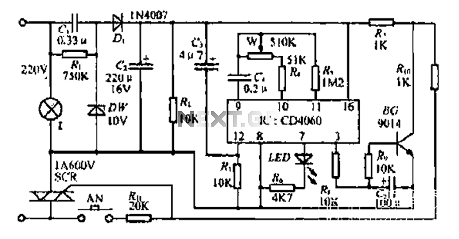
The circuit includes a CD4 component with a connection of 16 feet for the Vcc terminal, 8 feet for the ground, 12 feet for the reset terminal, 7 feet for the Qt end, and 3 feet for the Q...

This design outlines a sensor circuit that utilizes an LED as a light sensor. The operational control and amplification of the output are managed by a 1458 integrated circuit (IC), which functions as an operational amplifier (op-amp). The circuit...
When the ON/OFF button is pressed once, the equipment goes on and stays on. It goes off when the button is pressed again. The circuit is straightforward. It uses a JK CMOS Flip-Flop with its JK terminals tied high...
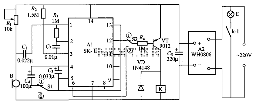
The circuit consists of an acoustic sensor, SK voice circuit, relay control circuit, vocal music circuit, and an AC buck rectifier circuit. The described circuit integrates several key components, each serving a distinct function to achieve the desired operational characteristics....