
Stepper Motor Controller

Stepper motors are electromechanical devices that convert electrical energy into precise mechanical movement. They are widely used in applications requiring accurate positioning and repeatability, such as in robotics, CNC machines, and 3D printers. The various versions and sizes of stepper motors allow for flexibility in design and application, accommodating different torque and speed requirements. Operating voltages for stepper motors can range from low-voltage options suitable for battery-operated devices to higher voltages for industrial applications, enhancing performance and efficiency.
A general-purpose stepper motor controller can manage multiple stepper motors simultaneously, providing control over speed, direction, and position. The controller typically interfaces with a microcontroller or a computer, translating commands into electrical signals that drive the motors. Key features of a stepper motor controller include pulse width modulation (PWM) for efficient power delivery, current limiting to protect the motor from overheating, and microstepping capabilities to improve resolution and smoothness of motion.
In a typical schematic, the controller would include input terminals for receiving control signals, a power supply input for the motors, and output connections to the stepper motors. Additional components may include transistors or MOSFETs to switch the motor phases, diodes for flyback protection, and capacitors for filtering noise from the power supply. Proper layout and grounding techniques are essential to ensure reliable operation and minimize electromagnetic interference (EMI). The design must also consider thermal management to prevent overheating during extended operation.
Overall, a well-designed stepper motor controller enhances the performance of stepper motors, enabling precise control in a wide range of applications.Stepper motors are available in several versions and sizes with a variety of operating voltages. The advantage of this general-purpose controller is that.. 🔗 External reference
Related Circuits
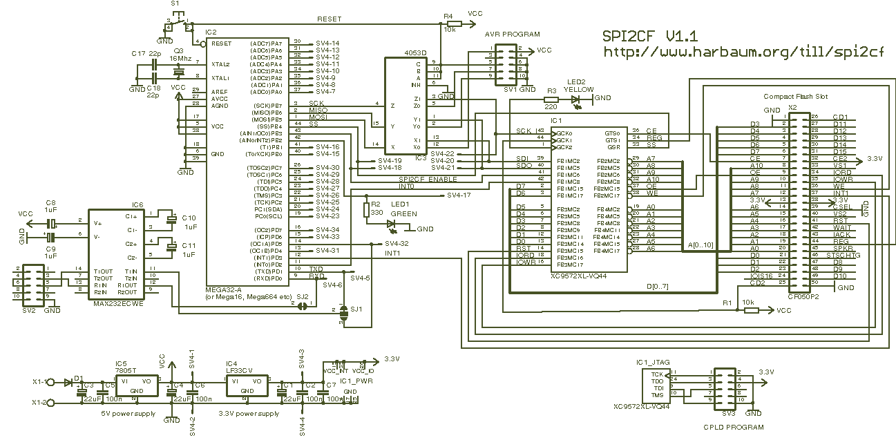
The page is about equipping an Atmel AVR microcontroller based system with a Prism WLAN interface. This document is intended for people that already have experiences with the AVR microcontrollers and teaches them how to add a cheap but...
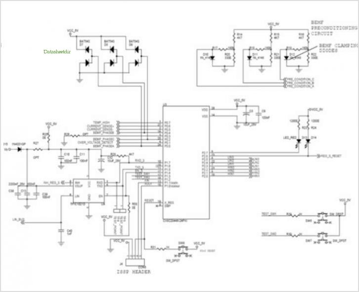
This application note outlines a driver solution utilizing the Zetex ZXLD1362 LED Driver IC, specifically designed for automotive electromagnetic compatibility (EMC) compliance. The ZXLD1362 switching regulator maximizes the efficiency of LED lighting solutions in automotive applications while minimizing component...
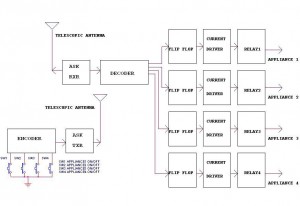
This circuit illustrates a remote control circuit diagram using RF technology without the use of a microcontroller. Features include a simple remote control circuit that operates via radio frequency. The remote control circuit operates by transmitting signals through radio waves,...
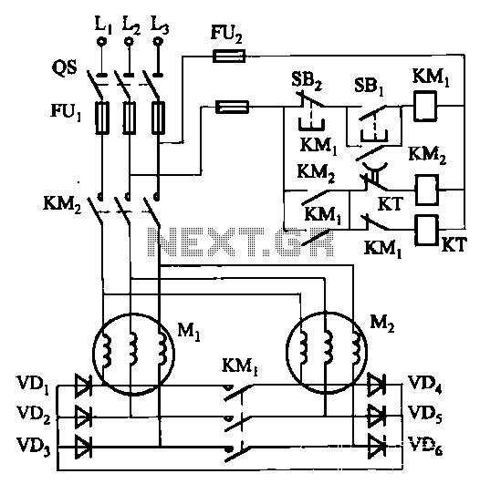
The circuit depicted in Figure 3-157 is designed for motors with a capacity of no more than 11 kW, requiring precise stopping capabilities. Upon shutdown, contact KMi releases, and the motor stator windings are configured into a three-phase rectifier...
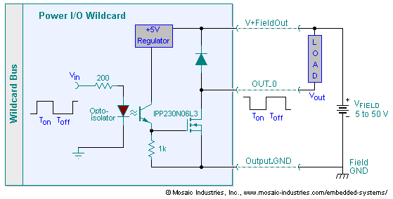
The embedded I/O board offers isolated high voltage switch inputs and eight high current, high voltage DC outputs. It utilizes optically isolated, open drain N-MOSFET transistors functioning as solid state relays (SSR) to control various resistive or inductive loads....
This resource contains step-by-step information for creating an AVR microcontroller programmer, complete with a suitable circuit diagram. This programmer is capable of programming 8051, AT89XX, AT90XXXX, and 8031 family microcontrollers. The AVR microcontroller programmer described is designed to facilitate the...