
stepper motor driver circuit diagram

The L297-L298 stepper motor control circuit is designed to manage the operation of stepper motors effectively. The L297 serves as the controller, generating the necessary signals to drive the L298 power driver, which provides the current to the motor coils. The circuit can handle both bipolar and unipolar stepper motors, making it versatile for various applications. The maximum current rating of 2 A ensures that the circuit can power motors with significant torque requirements.
In operation, the L297 processes input signals that determine the stepping mode, allowing for either full-step or half-step operations. Full stepping provides maximum torque, while half stepping increases resolution and smoothness of motion, which is particularly useful in applications requiring precise positioning. The TTL compatibility of the inputs allows for easy integration with microcontrollers or other digital logic devices.
The IC3 divider plays a crucial role in generating a stable clock signal, which is essential for maintaining consistent step timing. By programming the output from a computer or microcontroller, the desired step frequency can be achieved, enabling the motor to operate at various speeds. The SYNC output from the L297 can be used to synchronize other components in the system, ensuring that all parts of the circuit operate in harmony.
The jumper block K1 provides flexibility in selecting clock frequencies, with seven options available. This feature allows users to tailor the motor's performance to specific requirements, whether that be for high-speed operation or precision control.
The power supply requirements of 5 to 40 V highlight the need for adequate filtering, ensuring that voltage fluctuations do not affect the performance of the circuit. While stabilization of the power supply is not mandatory, it is advisable to implement filtering to mitigate noise, which could lead to erratic motor behavior. It is important to note that as the supply voltage increases, the maximum frequency of the steps can also increase, but care must be taken to remain within the specified limit of 40 V to prevent damage to the components.
Overall, the L297-L298 stepper motor control circuit provides a robust solution for controlling stepper motors in various applications, combining flexibility, precision, and ease of integration.Using L297-L298 integrated circuits manufactured by SGS Thomson (ST) can be made a control circuit for a stepper motor with two phase bipolar or unipolar four-phase (maximum current allowed on stage is 2 A). This integrated motor driver generates control signals for the double stator and allows selection of travel direction and execution of a full
step or half step, through proper planning its inputs, TTL compatible. Another component of the assembly, IC3 divider, is designed to provide the clock signal when the output of the computer could be programmed to branch to step frequency required. Order cycle for a given signal SYNC divider taken from L297, and the block of jumpers K1 allows selecting one of the 7 available clock frequency (frequency step).
5 and 40 V power supply should not be stabilized but is required filtering. Maximum frequency of the steps increases with voltage, but not exceeded its limit of 40 V. 🔗 External reference
Related Circuits
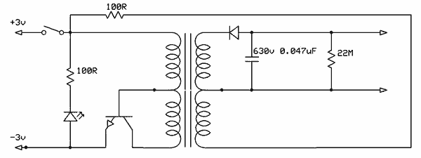
This circuit utilizes the widely available LM3914 integrated circuit (IC). The IC is straightforward to operate, does not require external voltage regulators due to its built-in voltage regulation feature, and can be powered from nearly any voltage source. The LM3914...
Free energy motors and generators are available for purchase, featuring plans for overunity devices. These devices resemble oscillators used in Joule thief circuits, although there may be some errors present in the designs. However, the concept remains clear. Free energy...
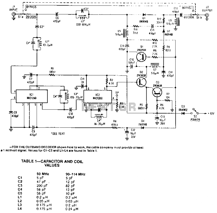
The circuit amplifier and attenuator control video detector consists of a composition for the synchronization channel. The synchronization interval is where the gain circuit is increased. The described circuit involves an amplifier and an attenuator that work together to control...
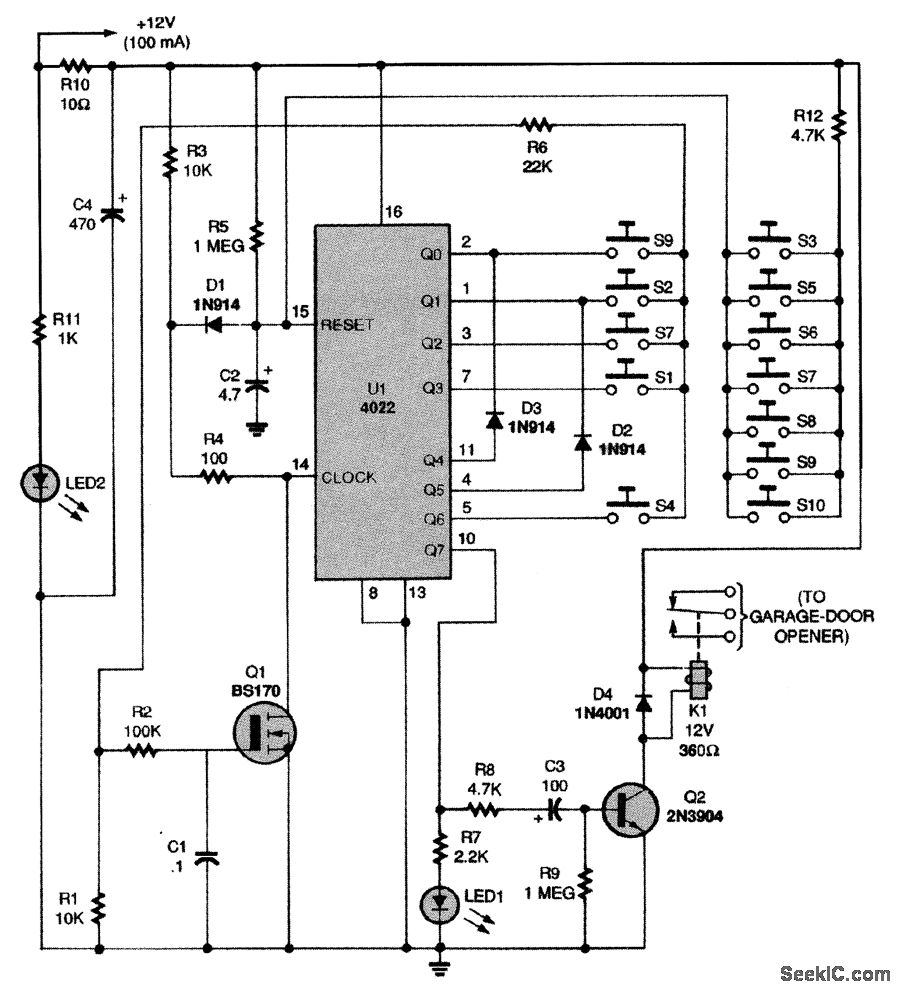
This circuit relies on the input of a correct sequence code. An incorrect number that is not part of the code triggers a reset of the circuit. When the correct code is entered, Q2 activates relay K1 for a...
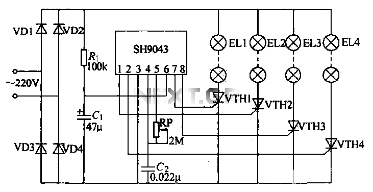
This example demonstrates a robust design featuring novelty lights that flash in a specific sequence, utilizing a 1-3-2-4 vault chase mode. The circuit includes diodes VD1 to VD4, which form a bridge rectifier, converting AC voltage to a full-wave...
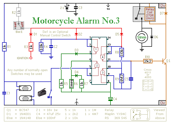
This circuit features an intermittent siren output and automatic reset. It can be operated manually using a key-switch or a hidden switch; but it can also be wired to set itself automatically when you turn-off the ignition. By adding...