
Stepper Motor Encoder Circuit

The described circuit utilizes an operational amplifier (op-amp) configured with bipolar stepper motor feedback to create a basic rotary encoder. The op-amp serves as a comparator, where the feedback from the stepper motor's coils is processed to determine the direction of rotation. The inclusion of two diodes in the feedback loop allows for separate paths for positive and negative feedback, enabling the circuit to differentiate between the two states based on the polarity of the output.
In this configuration, when the stepper motor produces a positive voltage output, the upper transistor is activated, illuminating one of the two LEDs. Conversely, when the output is negative, the lower transistor is triggered, lighting the other LED. This visual feedback indicates the direction of rotation, with each LED corresponding to a specific state of the motor's position.
The resistor (R) in the circuit plays a critical role in establishing a dead band at low frequencies. By adjusting the resistance value, the circuit can be tuned to prevent both LEDs from being illuminated simultaneously when the motor is at rest or rotating very slowly. This feature enhances the precision of the encoder by ensuring that it only registers distinct states during motion.
For optimal performance, the circuit can be adjusted for different output frequencies by modifying the capacitor (C) value. The original design specified a 100kΩ resistor and a 470nF capacitor, allowing the circuit to respond to rotations as slow as one-third of a revolution per minute (RPM). Reducing the capacitance will enable the circuit to handle higher frequencies, thus improving the responsiveness of the encoder.
To visualize the operation of the encoder, an oscilloscope can be employed in X-Y mode, where one output is connected to the X-axis and the other to the Y-axis. This setup will display the encoder's states as the motor rotates, illustrating the transitions between the various states (A, B, C, D) and providing insight into the encoder's performance in both clockwise and counterclockwise directions.
It is important to note that while this circuit can effectively utilize a stepper motor as a rotary encoder, there are inherent limitations, particularly at low speeds where output may be minimal. This necessitates a careful balance between high-speed and low-speed operation. In contrast, conventional encoders often employ optical sensors, which can provide consistent performance across a wider range of speeds, although they may introduce jitter at lower velocities.The circuit is a simple op-amp but with two diodes (the transistor b-e junctions in the feedback to split the feedback for positive and negative outputs. On positive output from the stepper coil the top transistor tuns on, on negative, the bottom. One or other LEDs lights for each polarity. Resistor R can be omitted: its function is to allow a dead band at the centre/low frequency. Without it one or other LEDs is always on. With it, output C will be at centre point for very low rotation or stopped stepper. It is quite possible to use a small stepper motor as a rotary encoder. Here's a circuit I knocked up when, I was designing automatic welding machine controls, as a feasibility study. In fact the idea was never used, so I never designed logic to process the signals. It uses a bipolar stepper (with two windings, or 'phases'). Only one phase of the stepper is shown here - you will need to duplicate this circuit for the second winding.
In the original we had R at 100K and C as 470n: the circuit responded as low as 1/3 r.p.m. You will have to reduce C for higher output frequencies. If you use a scope in X-Y mode with Y deflection on one circuit output 'Z' and X on the other circuit, you can clearly see the states of the 'encoder' as in the state diagram below. At A both outputs are high, and at C both are low. At rest (with R present) it is at state O. When rotating the points A,B,C,D can all be seen and will occur in one direction for clockwise rotation or reversed for anticlockwise.
The problem with a stepper (or any other motor) used as a generator is that at very slow speeds it gives virtually no output - so there is a problem with slow speeds. You have to make some sort of trade off between high speed and low speed performance. Proper encoders use optical switches which work at any speed. Of course their problem at slow speeds can be jitter. 🔗 External reference
Related Circuits
This circuit is designed to detect the approximate percentage of salt in a liquid. After careful calibration, it can provide a quick, rough indication of salt content in liquid foods for dietary purposes. The operational amplifier IC1A is configured...
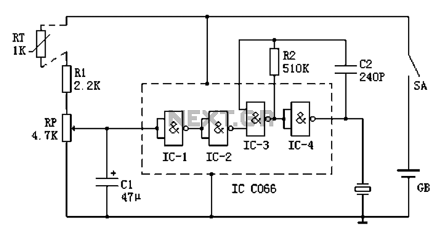
The circuit diagram illustrates a five-use tri-state audio logic pen utilizing components such as the CD4066 and a 555 timer. The primary elements include a multivibrator, a four-way switch (CD4066, designated as IC1), and a gate circuit formed by...
Boiling water on a kitchen gas stove can lead to issues such as spilling boiling water if the process is not monitored, which can extinguish the flame and cause gas leakage. A notification device can address this problem. The...
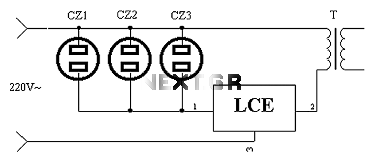
The application circuit operates as depicted below. It typically utilizes a shared TV antenna amplifier and an isolated power switch for the user. There are instances when the TV may not function, yet the antenna amplifier remains powered, leading...
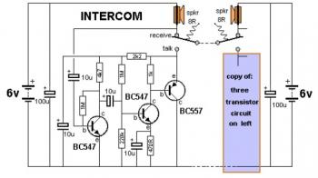
This is a two-station simple intercom circuit built using transistors and common 8-ohm mini speakers. The speaker functions as a microphone and generates sound, eliminating the need for a separate microphone in this intercom setup. The "press-to-talk" switches should...
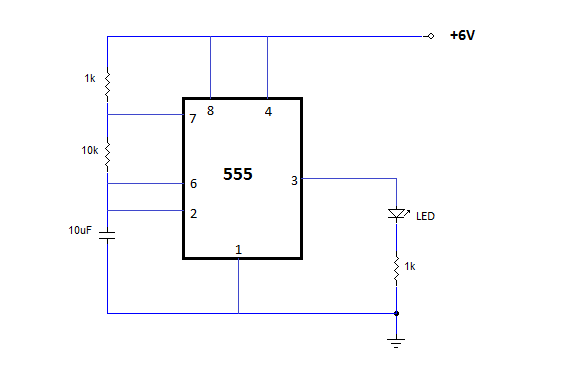
The NE555 is one of the most commonly used timer integrated circuits (ICs). It is a monolithic timing circuit capable of producing accurate and highly stable time delays or oscillations. Similar to general-purpose operational amplifiers, it is reliable, easy...