
Stereo balance tester

The described circuit is a stereo balance meter that provides visual feedback on the audio signal levels from a stereo amplifier setup. The zero-center meter is crucial for indicating whether the audio signals from the left and right channels are balanced. When both channels are equally powered, the meter should ideally read zero, which signifies that the audio output is in phase and that both speakers are matched in terms of output level.
The choice of using five percent tolerance resistors ensures that the circuit maintains a reasonable degree of accuracy in its readings, minimizing errors that could arise from component variations. Matched diodes are essential in this circuit to ensure that the signal processing remains consistent, as any discrepancies in diode characteristics could lead to incorrect readings on the meter.
In practical applications, if the meter displays a reading away from zero, it indicates a potential issue with the audio setup. This could be due to mismatched speaker impedances or incorrect wiring configurations, which can cause phase issues. To troubleshoot, it is recommended to check the connections to ensure that the meter leads are properly connected to the amplifier's hot terminals. The common leads should be securely grounded to provide a stable reference point for the measurements.
This balance meter circuit can be integrated into various audio systems to enhance user experience by allowing for easy adjustments to achieve optimal sound quality. Proper calibration and setup are vital for ensuring that the meter functions accurately, thereby facilitating the correct adjustment of audio levels for an immersive listening experience.The meter will show volume and tone control balance between left and right stereo amplifiers. For maximum convenience the meter is a zero-center type. Resistors are five percent or better and the diodes a matched pair. Optimum stereo level and phase balance occurs for matched speakers when the meter indicates zero. If the meter indicates either side of zero, the levels are not matched or the wires are incorrectly phased. Check phasing by making certain the meter leads are connected to the amplifier hot terminals and the common leads go to ground.
Related Circuits
This is a simple servo tester which will comprehensively test the capabilities of almost any modern servo. It has two pushbuttons, CENTRE and SWEEP and a potentiometer which works as follows: CENTRE Does exactly that, centers the servo, afterwards...
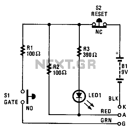
The cathode, anode, and gate of the Device Under Test (DUT) are connected to the unit's K, A, and G terminals, respectively. Pressing switch S1 supplies a gate current to the DUT, triggering it to turn on. Resistor R1...
This preamplifier is designed to interface with CD players, tuners, tape recorders, and similar devices, providing an AC voltage gain of 4 to drive less sensitive power amplifiers. Given that modern Hi-Fi home equipment often comes with small loudspeaker...
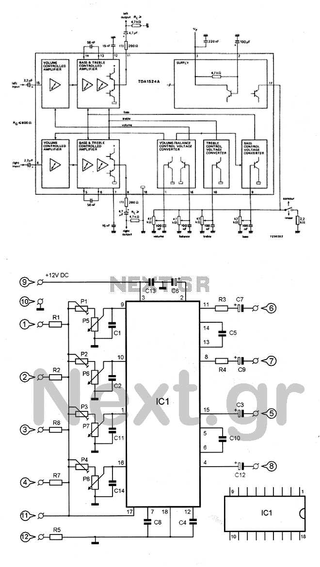
The circuit utilizes the TDA1524 chip, which is an integrated control unit for volume, bass, treble, and balance adjustments. Control is achieved through four potentiometers (P5-P8). The integrated circuit IC1 requires very few external components to operate. Potentiometers P1-P4...
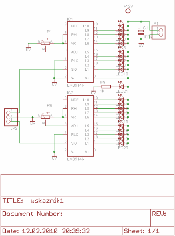
The LM3914 is a monolithic integrated circuit designed to sense analog voltage levels and drive a 20 LED stereo VU meter. It features a circuit diagram for a PCB layout using Eagle software, specifically for a 10 LED stereo...
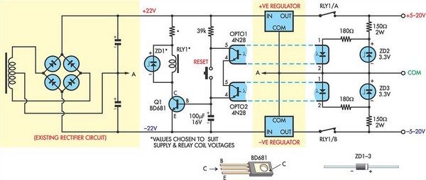
This circuit was designed to protect a dual rail power supply from shorts across the two rails. It uses an optocoupler to monitor each supply rail, with the internal LEDs powered from ZD2 and ZD3 and the associated resistors....