
Thermometer circuit with AD595

The circuit consists primarily of integrated circuits, which facilitates a streamlined assembly process on the circuit board, optimizing for soldering efficiency. The design utilizes a nixie tube for displaying temperature readings, specifically employing only three pins from the third nixie tube to represent the hundreds position. This decision conserves space and components, leading to the choice of using high-voltage transistors (MPSA42) in lieu of a 74141 integrated circuit. This approach is predicated on the assumption that the thermometer will not need to display temperatures exceeding 399 degrees, thus simplifying the design without compromising functionality for the intended range.
A critical component in the circuit is the AD595 thermocouple amplifier, designated as IC4. While alternative methods could achieve similar results with passive components such as resistors and custom programming, the AD595 was selected for its ease of integration and additional features that may be leveraged for future enhancements. The AD595 is notable for its ability to handle non-linearities inherent in thermocouple outputs, providing a straightforward formula to facilitate accurate temperature readings. The selection of this integrated circuit reflects a balance between immediate requirements and potential future applications, ensuring that the design remains versatile and adaptable.the entire circuit is comprised of integrated circuits. This makes for some easy organization when it goes to the circuit board for soldering. In addition, I used only 3 of the pins on the 3rd nixie tube for the hundreds position in the display. Since I was only using three, I decided to save a 74141 IC and just use a few high voltage transistors (MPSA42).
I figure the thermometer will very unlikely be in any situation where a temperature between 0 and 399 will ever need to be displayed, and if it is, the electronics will probably not work anyways. The other thing to point out here is IC4, the AD595 thermocouple amplifier. Again, here I could have easily done this without purchasing somewhat of a costly IC. A few resistors and a little more creative programming allows for pretty much the same result. However, at the time I hadn't really thought that through all the way and this seemed like an easy and quick solution. The AD595 also has many other features which in the future could be used to do some fun stuff with. Check out the spec page for details. The AD595 also provides a simple formula for dealing with non-linearities in the thermocouple. 🔗 External reference
Related Circuits
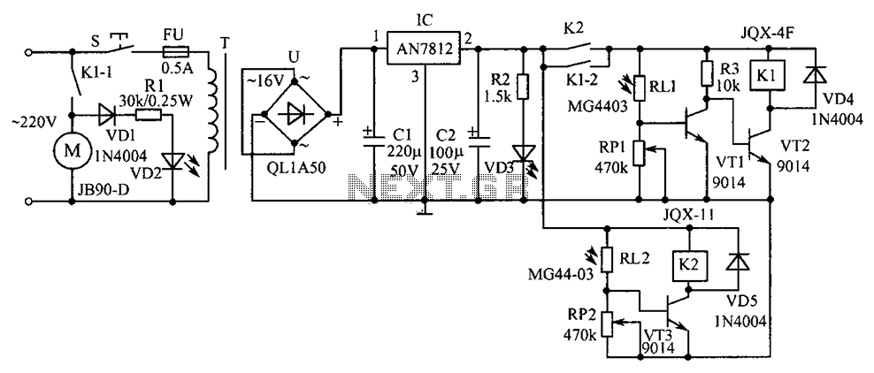
Commonly used in industrial and mining enterprises, a power mixer is employed for mixing materials. Due to the presence of odors or dust, operators should maintain a safe distance from the equipment. The system utilizes light control for operation....
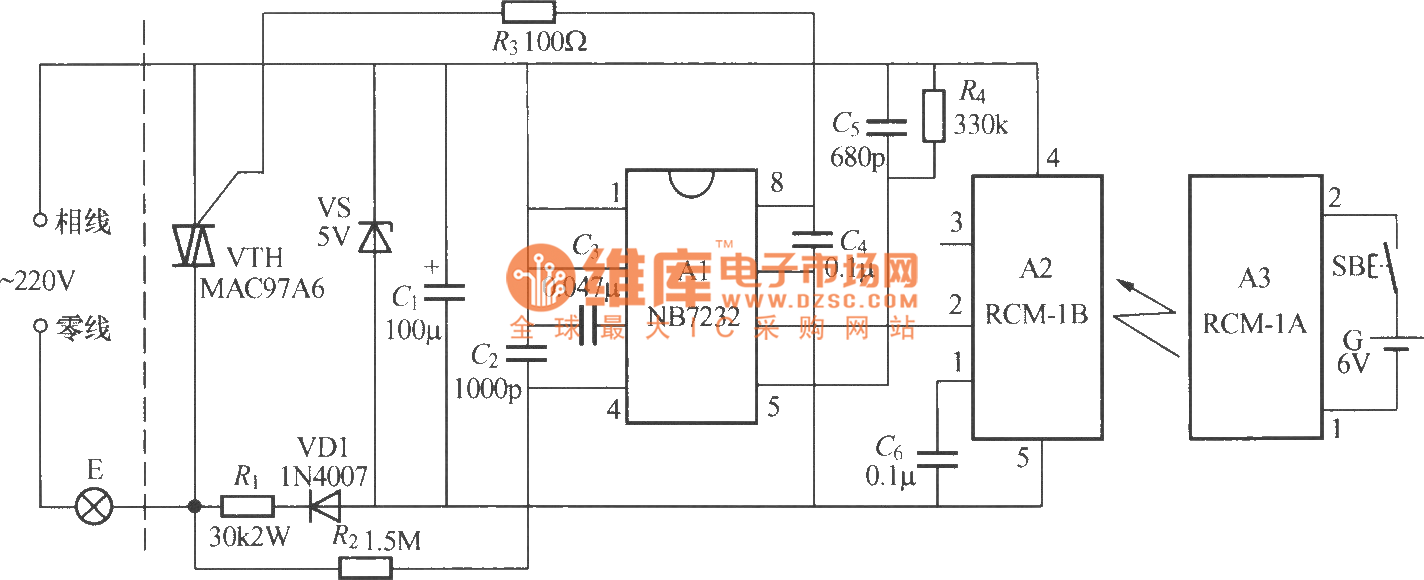
The diagram above illustrates a radio remote control dimmer circuit. This circuit utilizes a micro radio transmit/receive module in conjunction with a light modulation ASIC, resulting in a compact and easily producible design. It operates reliably and features a...
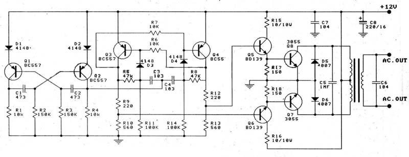
This circuit is a 100W DC inverter based on a transistored multivibrator and serves as a transistor signal amplifier. The inverter converts a 12V DC input voltage to approximately 220V AC. It is recommended to use a 12V car...
The circuit diagram represents a water-activated relay circuit. This circuit employs two transistors configured as a high-gain compound pair. The transistors used are 2N2222A for T1 and T2, which may also be substituted with BC108. The current gain is...
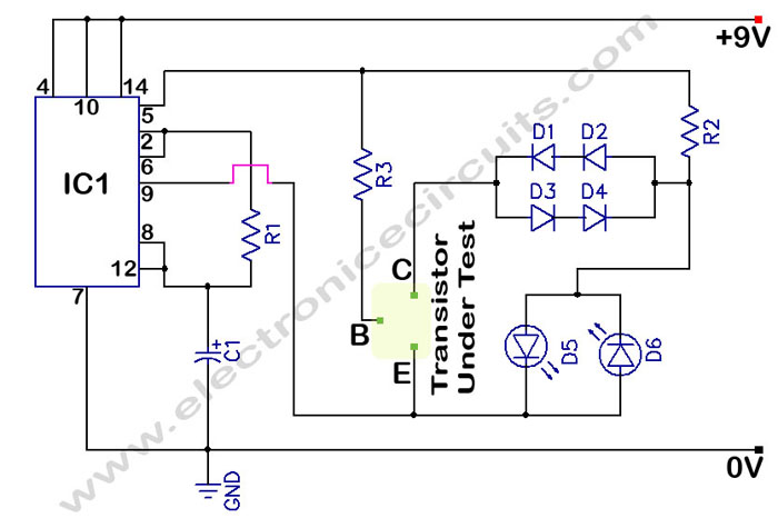
In a circuit transistor tester schematic, there is a circuit that can indicate the condition of a transistor using two LEDs. A good NPN transistor... The circuit transistor tester is designed to evaluate the functionality of both NPN and PNP...
A potentiometer regulates the firing point of the triac. Capacitor C4 is charged through resistors R3, R4, P1, and R5. After a specific duration, determined by the potentiometer setting, the charge in C4 becomes sufficient for the diac D...