
Capacitive load drive circuit diagram of the MAX4100 4101

The MAX4100 and MAX4101 are high-speed operational amplifiers designed for applications requiring high bandwidth and fast response times. When driving capacitive loads, these amplifiers can experience stability issues, leading to undesirable behavior such as overshoot and ringing. This is particularly prevalent when the capacitive load exceeds the specified limits of 5pF for the MAX4100 and 20pF for the MAX4101.
To address these stability challenges, the isolation resistor Rs is strategically placed between the output of the amplifier and the capacitive load. This resistor acts as a damping element, effectively reducing the Q-factor of the output stage and thereby minimizing the potential for oscillations. The recommended value for Rs is typically less than 50 ohms, as this range has been found to provide adequate suppression of overshoot while maintaining signal integrity.
In practical applications, the choice of the isolation resistor value may depend on the specific load characteristics and the desired performance of the circuit. It is advisable to experiment with different resistor values within the specified range to achieve optimal performance for a given application. Additionally, careful consideration should be given to the layout of the circuit, as parasitic capacitance and inductance can further influence the stability and performance of the amplifier when driving capacitive loads. Proper PCB design techniques, such as minimizing trace lengths and using ground planes, can help enhance the overall performance of the circuit. As shown in FIG grounds MAX4100/4101 using a capacitive load drive circuit isolation resistor Rs constituted. MAX4100/4101 allows the maximum capacitive load, respectively 5pF and 20pF, more than likely to overshoot and ringing oscillation. The circuit between the output terminals and the load plus an isolation resistor Rs, for suppressing overshoot and ringing oscillations, in most cases, Rs resistance is less than 50 sufficient.
Related Circuits
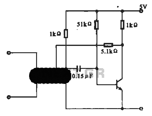
This circuit illustrates an oscillator that is controlled by an optocoupler, utilizing photoelectric coupling to drive a transistor. The oscillator circuit described operates by employing an optocoupler to provide electrical isolation between its input and output stages while allowing control...

This is an application circuit for calibration known as a high voltage AC calibrator circuit. A key aspect of sine wave oscillator design is the stable control of amplitude. In this circuit, the amplitude is stabilized through servo control,...
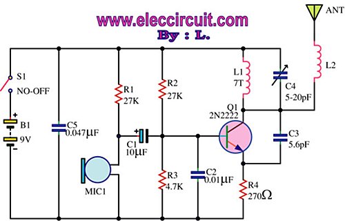
This is an FM wireless transmitter circuit designed to operate a microphone without the need for a cable connecting the microphone to the amplifier. The FM wireless transmitter circuit typically consists of several key components: a microphone, an oscillator, a...
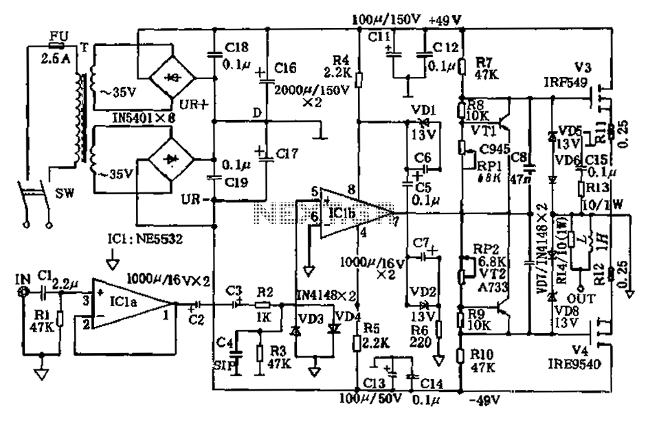
The amplifier circuit presented in this paper introduces a floating power supply aimed at increasing output power. The output power of the amplifier is influenced primarily by the final stage amplifier supply voltage. The circuit's principle is illustrated in...
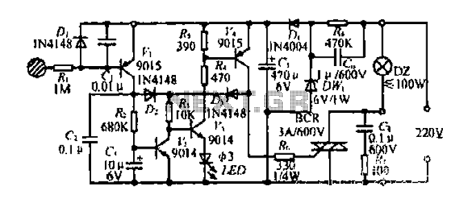
Diagram 2 depicts a shake tube circuit with a capacitance (C) and a trigger voltage rectifier filter element. The circuit includes a trigger voltage transistor amplifier (H), three pull tubes (n, U, v), and utilizes a thyristor as a...
Also known as a megger insulation resistance meter, this device measures resistance at the megohm level. It is primarily used to assess the insulation resistance of motors, electrical circuits, and equipment. Additionally, it helps determine whether there is circuit...